Quantification
The availability of this feature depends on the camera model.
Introduction
Quantitative Optical Gas Imaging (QOGI) extends Optical Gas Imaging (OGI) to provide a quantitative result. While OGI can qualitatively detect the presence of a gas leak, QOGI will quantify the gas leak and provide a measurement of leak rate or concentration.
Quantification mode is specially designed to be used for QOGI applications. The data acquisition and analysis is integrated in the camera and the quantification results are displayed on the camera screen. The results are automatically saved and can also be saved as a pdf.
The camera can be set up to record a radiometric video as part of the quantification measurement. The video file, which also includes the quantification parameters, is automatically saved in the camera. You can transfer the video file with the quantification parameters to another device, such as the FLIR QL320, for further processing.
Field equipment
The plume extraction algorithm is change based, therefore it requires a steady image to separate the plume from the background. This requires the operator to place the camera on a tripod to perform any quantification measurement.
In addition to the tripod, a thermometer and a tape measurer (or infrared range finder) are recommended as the operator will need to provide the ambient temperature and distance from the camera to the leak.
An anemometer is also recommended, though not absolutely required. The operator will provide an estimate of the wind conditions (calm, normal or high), not an exact wind speed measurement.
User interface
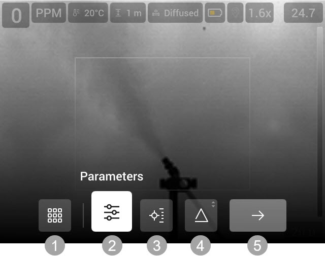
Mode selection
Parameters
Measurements
Delta T
Start measurement
Quantification parameters
For accurate quantification results, it is important to set the quantification parameters according to the current conditions.
Temperature refers to the temperature of the gas. It is common to use the ambient temperature to represent the gas temperature. The assumption being made is that the gas will quickly equilibrate to ambient temperature, even if there is a pressure drop at the leak source.
Wind refers to the current wind conditions. There are three options: High (> 10 mph), Normal (2-10 mph), and Low (0-1 mph). These general wind conditions are meant to describe the dispersion qualities of the plume being measured. It is not necessary to make an exact wind speed measurement, the setting is rather a description of the general conditions.
Leak type refers to the geometry of the leak. There are two options: Diffuse and Point. A Diffuse leak is one whose source is greater than 5 cm (2 in.) in diameter. An example of a diffuse leak is a thief hatch on a storage tank. A Point leak is one whose source is less than 5 cm (2 in.) in diameter. An example of a Point leak is a fitting on a ¼" tubing.
Distance refers to the distance from the camera to the leak.
Gas type refers to the gas composition being measured.
Gas plume refers to the polarity of the plume being measured. Considering white to be hot, a Black plume will appear colder (or darker) than the background. It is typical to have a Black plume when the apparent temperature of the background is warmer than the ambient temperature. A White plume appears warmer (or brighter) than the background. It is typical to have a White plume when the apparent temperature of the background is colder than ambient temperature.
Type of measurement
The camera allows you to measure both flow rate and concentration. For more information, see section Leak rate versus concentration.
To select the type of measurement, do the following:
On the main toolbar, select Measurement. This displays a toolbar.
On the toolbar, do one of the following:
Select Concentration. This displays a box on the image and a toolbar where you can do the following:
To resize the box, select Resize box and push the joystick. Move the joystick up/down and left/right to resize the box.
To move the box, select Move box and push the joystick. Move the joystick up/down and left/right to move the box.
To reset the box to default size and position, select Reset box.
When completed, select Done.
Select Flow rate. This displays a circle on the image.
Delta T
The background should be at least 2°C (3.6°F) warmer (or colder) than the ambient temperature to provide sufficient contrast for quantification. Use the Delta T feature to show areas of the field of view where there is insufficient delta temperature for quantification. Those areas will be highlighted red.
For more information, see sections Ensure minimum delta temperature and Assessing delta temperature.
Flow rate unit
To change the flow rate unit, select Settings > Quantification > Flow rate.
Radiometric video recording
The camera can be set up to record a radiometric video (*.csq) after the quantification measurement. The video file, which includes the quantification parameters, can be opened and processed on another device, such as the FLIR QL320.
To enable recording of radiometric video (*.csq), select Settings > Quantification > Save radiometric recording = On.
Perform a quantification measurement
In a typical field use, the camera will be used as a hand-held camera to first identify a gas leak. To measure the leak, the operator will select a measurement position and place the camera on a tripod and then perform a quantification measurement.
Main steps
The quantification measurement includes the following main steps:
Select a measurement position.
Place the camera.
Ensure minimum delta temperature.
Set the quantification parameters.
Start the measurement.
Select a measurement position
Observe the leak from several positions to find a viewing angle that gives the camera the best measurement position. Fore more information, see section Measurement position.
Place the camera
Set up the tripod at the viewing location you have chosen.
Choose the height and location of the tripod to optimize the background as described in section Measurement position.
Position the camera so the identified leak location is centered in the camera’s Field of View (FOV).
Aim the camera so that the gas leak is inside the circle on the screen. Make sure that all gas flows out of the circle. See also section Field of view and focus.
Adjust the camera focus so that both the plume and the background are in focus. If this is not possible, priority should be given to the plume. See also section Field of view and focus.
Make sure the camera is operating in the proper temperature range. See also section Camera temperature range.
Enter Quantification mode
To enter the Quantification mode, select Quantification on the Mode selection menu.
Set the quantification parameters
Before each measurement it is important to check and set the quantification parameters according to the current conditions.
Measure parameters
Measure the ambient temperature every time a quantification measurement is performed. For more information, see section Measure Ambient Temperature.
Enter parameters
For accurate quantification results, it is important to set the quantification parameters according to the current conditions. For more information, see section Quantification parameters.
To enter the quantification parameters, do the following:
On the main toolbar, select Parameters. This displays a toolbar.
On the toolbar, select a parameter. This displays a dialog box, where you can change the parameter value.
To close the dialog box, push the Back button.
Ensure minimum delta temperature
The background should be at least 2°C (3.6°F) warmer (or colder) than the ambient temperature to provide sufficient contrast for quantification. For more information, see section Assessing delta temperature.
Use the Delta T feature to show areas where there is insufficient delta temperature for quantification.
On the main toolbar, select Delta T. This displays a dialog box.
In the dialog box, you can define the settings:
Turn on/off the Delta T feature.
Atmospheric temperature: The current ambient air temperature in the same general area as the gas leak.
NoteThis setting is the same as for the measurement parameters, see section Measurement parameters. Any changes in the Delta T dialog will also change the corresponding measurement parameter setting.
Temperature difference: Set the temperature difference to 2°C (3.6°F).
To close the dialog box, push the Back button.
Start the measurement
Do not move or shake the camera while measuring the gas. This will ensure a better measurement result.
To start and run the measurement process, do the following:
On the main toolbar, select Start measurement.
The camera displays the progress on the screen.
If video recording is enabled, a red dot is displayed while the recording is in progress.
When the measurement and documentation are completed, you can select to view a summary of the quantification result.
The quantification results are automatically saved to the memory card.
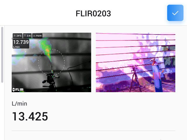
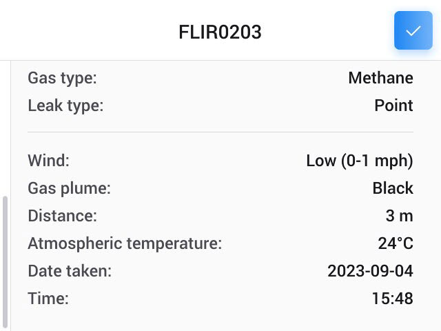
Figure 1. Summary of the quantification result
Quantification results
The camera saves the quantification results in the active folder in the image archive.
The following files are saved:
Thermal image, including a summary of the quantification result.
Visual image.
-
If recording is enabled: Video (*.csq) file, including the quantification parameters. For further processing, transfer the video (*.csq) file to another device, such as the FLIR QL320.
View summary
The quantification thermal image includes a summary of the quantification result.
To view the summary of the quantification result in the camera, do the following:
On the Mode selection menu, select Gallery.
Go to the active folder.
Select the quantification thermal image you want to view.
Push the joystick or tap the screen. This displays the top toolbar.
On the top toolbar, select
 . This displays the right toolbar.
On the right toolbar, select
 . This displays the summary.
Save quantification files as a pdf report
To save the summary of the quantification as a pdf, do the following:
On the Mode selection menu, select Gallery.
Go to the active folder.
Select the quantification thermal image you want to view.
Push the joystick or tap the screen. This displays the top toolbar.
On the top toolbar, select
. This displays the right toolbar.On the right toolbar, select
 .
.A pdf report is created.
Transfer quantification files
The quantification files are stored on the memory card.
You can upload the quantification files to your FLIR Ignite account or transfer the files manually using the USB cable or the memory card.
Practical information
Measurement position
Once a leak is identified, the operator will observe the leak from several positions to find a viewing angle that gives the camera the best measurement position to quantify the leak.
Factors to consider when determining the optimal viewing angle:
Ideally, you will want an unobstructed view of the leak location. If this is not possible, you will want an unobstructed view of the gas plume.
Selecting a suitable background is important as quantification requires sufficient thermal contrast. In general, the gas plume will be the same temperature as the ambient air temperature because the small amount of gas escaping from the equipment and entering the atmosphere will quickly equilibrate with ambient temperature. The background should be at least 2°C (3.6°F) warmer (or colder) than ambient temperature to provide sufficient contrast to quantify the plume. This is critical for an accurate measurement.
Select a location suitable for the camera. You will need to mount the camera on a tripod so look for a relatively flat surface within a reasonable distance of the leak.
It is best to place the camera at a distance somewhere between 5 to 15 feet for small leaks and from 20 to 40 feet for large leaks. See also section Distance and range.
Distance and range
Distance from the camera to the gas leak is another parameter you will need to enter into the quantification module. While the quantification feature is agnostic to range (i.e., the quantification feature will operate at any distance within the method limits), you must provide this distance for accurate quantification.
The range for the quantification feature is a function of the lens attached to the camera. For the 23 mm lens (24° FOV) the range is from 5 feet to 54 feet (1.5 to 16 meters). For the 38 mm lens (14° FOV) the range is from 8 feet to 90 feet (2 to 27 meters) For the 92 mm lens (6° FOV) the range is from 20 feet to 210 feet (6 to 64 meters). In general, small leaks should be measured near the bottom of the range and large leaks should be measured near the top of the range.
Measure Ambient Temperature
The ambient air temperature is one of the parameters you will need to provide to the quantification module. The measurement of this air temperature should be taken within the same general area as the gas leak, although it is not necessary to get into the midst of the gas leak. A measurement taken at the location of the camera is generally acceptable unless there is a significant temperature gradient between the leak location and the location of the camera. A measurement read off an instrument like a smart phone that gives the general temperature of the city is NOT recommended as local temperature can vary considerably (especially in close proximity to process equipment).
A few words of caution when obtaining the air temperature:
Do not place the thermometer in direct sunlight as the solar heating tends to bias the reading high.
Do not place the thermometer on the ground as this may not be representative of true ambient air temperature.
Ideally the thermometer should be placed in a position where it is exposed to the same free-flow ambient air conditions as the gas plume and free from potential interferences such as direct sunlight or other radiating heat sources.
It is strongly recommended that the ambient temperature be measured each and every time a quantification is performed.
Assessing delta temperature
Use the Delta T feature to show areas of the field of view where there is insufficient delta temperature for quantification. Those areas will be highlighted red.
If parts of the scene are below the minimum delta temperature, it may still be possible to perform a measurement. If you can position the camera so that the measurement ring is placed in a region of good delta temperature, then you can proceed with the measurement. If that is not possible, try changing the viewing angle. Recall that for quantitative optical gas imaging, both reflected energy and emitted energy contribute to the apparent temperature. It is often possible to change the apparent temperature just by changing the viewing angle to the background, thereby changing the amount of energy reflected to the camera. If you can find no angle or camera position that provides sufficient delta temperature, then you may not be able to perform a measurement. Returning to the site at a different time of day will often yield a different delta temperature.
Camera temperature range
For each background, you should check to see that the camera is operating in the proper temperature range. The camera will provide the upper and lower temperatures for each range and a visual indicator to show the distribution of the pixels in the image. If a majority of the pixels are near the top or the bottom of the temperature range, the operator should adjust the temperature range to obtain accurate quantification results. A common scenario where this becomes necessary occurs when the sky is used as a background. The sky typically has very little radiance in the mid-wave infrared. As a result, the apparent temperature of the sky can be quite low. It is often necessary to lower the temperature range of the camera when switching to a sky background.
Field of view and focus
A critical component of the leak rate measurement process is adjusting the field of view (FOV) for the camera. The camera should be positioned so that the leak location is in the center of the FOV. You should verify that the gas leak is in the center of the measurement boundary (i.e. the ring) and that the gas plume is flowing across the measurement boundary. In general, the best quantification results will be obtained if the leak originates in the center of the FOV with a clear field of view as the plume passes across the measurement boundary roughly perpendicular to the camera FOV.
In some cases, it is easy and obvious to determine the location of the leak. These leaks are emanating from a single location and the plume emanates from that single location. In other cases, the leak is emanating from a component such as a flange or valve without a clearly defined source. In these cases, centering the component in the FOV is sufficient.
The focus of the camera can potentially affect the measurement. The user should take care to ensure that both the leak site (leaking component or plume) as well as the background are in focus. This may or may not be feasible depending on the camera lens used (which determines the depth of field), the distance between the leak site and the background objects, and the distance to the camera. When it is not feasible to bring both the plume and the background into focus, priority should be given to the plume.
Leak rate versus concentration
The camera allows you to measure both flow rate and concentration.
Flow rate
When measuring flow rate (i.e. volumetric or mass emission rate), a ring is displayed on the image. The ring represents a flux boundary. The measurement result represents the amount of plume crossing this boundary.
The ring is always centered and the ring size generally cannot be changed. You will notice that the ring size does change as you change the distance or lens.
Concentration
When measuring concentration, a box is displayed on the image. You are now measuring a path averaged concentration rather than an emission rate.
The camera will report the maximum ppm-m concentration within the box. You can resize and move the box.
Method limits
The quantitative method in the camera has certain limits. For example, the method requires a minimum delta temperature of 2°C for accurate results. The method limits for distance are a function of the lens:
23 mm lens (24° FOV): 5 feet to 54 feet (1.5 to 16 meters)
38 mm lens (14.5° FOV): 8 feet to 90 feet (2 to 27 meters)
92 mm lens (6° FOV): 20 feet to 210 feet (6 to 64 meters)
In terms of release geometry, the current method works for point releases (2" diameter or less) and diffuse releases up to 12" in diameter. With respect to leak rate, the current method has been calibration from 0.2 sl/m up to 300 sl/m (methane). With respect to wind speed the calibration extends to 10 mph.