Pin configurations
Ethernet connector and cable
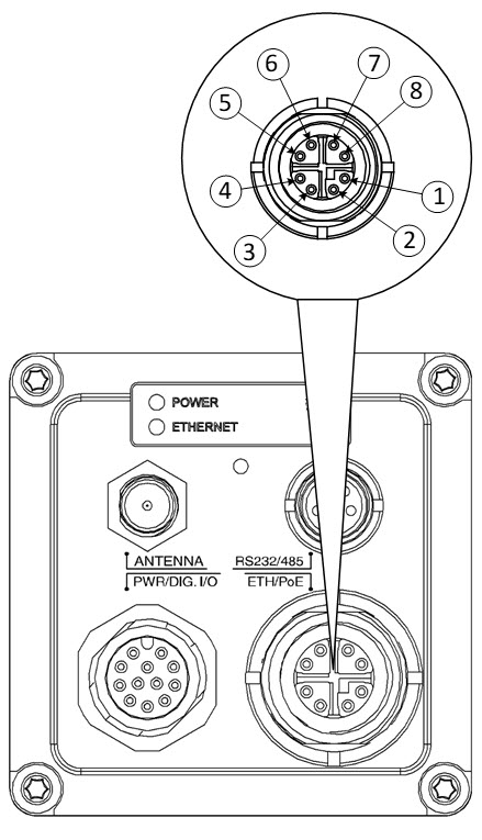
Figure 1. Female X-coded M12 Ethernet connector |
|||
|
Pin |
Configuration |
||
|
1 |
DA+ |
||
|
2 |
DA- |
||
|
3 |
DB+ |
||
|
4 |
DB- |
||
|
5 |
DD+ |
||
|
6 |
DD- |
||
|
7 |
DC- |
||
|
8 |
DC+ |
||
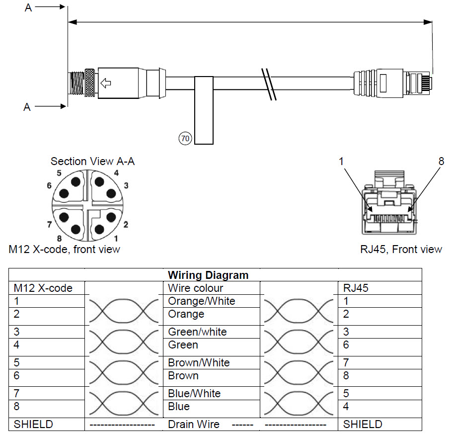
Figure 2. Ethernet cable M12 to RJ45
Power/Digital I/O connector and cable
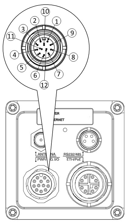
Figure 3. Male A-coded M12 Power/Digital I/O connector (T911852ACC & T911853ACC) |
|||
|
Pin |
Configuration |
||
|
1 |
EXTPWR_RTN |
||
|
2 |
EXTPWR_IN |
||
|
3 |
FAULT_A |
||
|
4 |
FAULT_B |
||
|
5 |
DIGOUT1A |
||
|
6 |
DIGOUT1B |
||
|
7 |
DIGOUT2A |
||
|
8 |
DIGOUT2B |
||
|
9 |
DIGIN1 |
||
|
10 |
DIGIN2 |
||
|
11 |
Not Connected |
||
|
12 |
DIGIN_RTN |
||
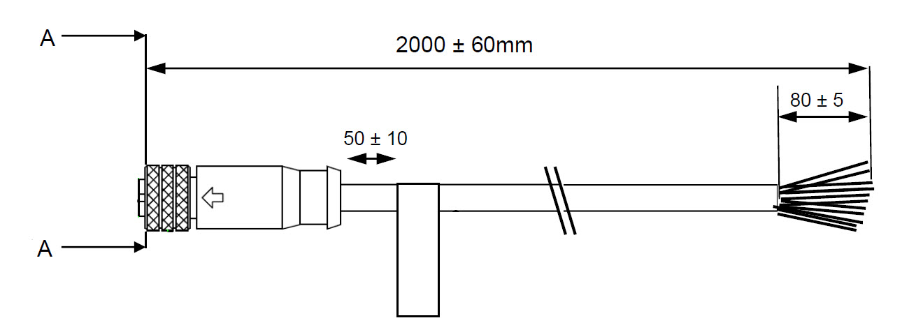
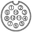
Figure 4. Cable M12 to pigtail |
Section A—A |
Wire colour |
|
|
1 |
Black |
||
|
2 |
Red |
||
|
3 |
Green |
||
|
4 |
Purple |
||
|
5 |
Yellow |
||
|
6 |
Pink |
||
|
7 |
Orange |
||
|
8 |
Brown |
||
|
9 |
White |
||
|
10 |
Grey |
||
|
11 |
Light blue |
||
|
12 |
Blue |
RS232/RS485 connector
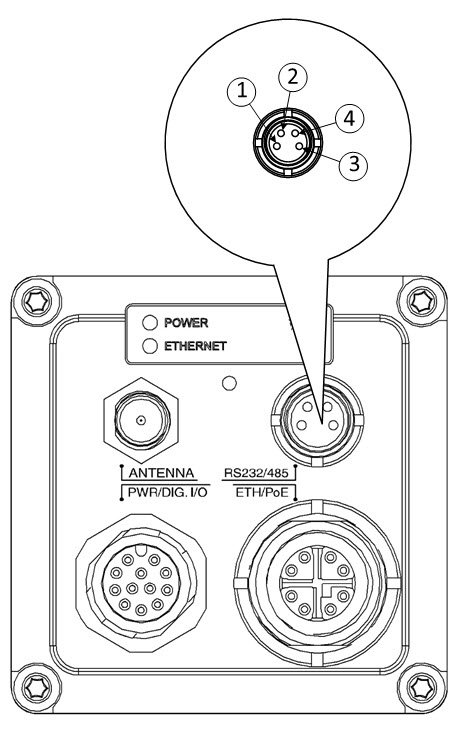
Figure 5. Male A-coded M8 RS232/RS485 connector |
|||
|
Pin |
Configuration |
||
|
1 |
RS232_TXD alt RS485A |
||
|
2 |
RS232_RXD alt RS485B |
||
|
3 |
Chassie GND |
||
|
4 |
Not Connected |
||