Camera web interface
Supported browsers
The camera web interface supports the following browsers and versions:
Google Chrome 77 and higher,
Microsoft Edge 17 and higher,
Mozilla Firefox 69 and higher.
Microsoft Internet Explorer is not supported.
Login
Log in to the camera web interface by using the IP address of your camera.
Follow this procedure:
Do one of the following:
Identify your camera by the MAC address (printed on the back of the camera) in FLIR IP Config, and then double-click it.
Type the IP address of your camera into the address bar of a web browser.
This displays the login view.
When logging in for the first time, log in with the username admin and the default administrator password provided by FLIR (available on the camera calibration certificate). It is possible to change the administrator password after the first login, and some cameras will require this.
-
Store the calibration certificate with the default administrator password in a safe place. If the new password is later on forgotten or lost, the camera needs to be reset to factory defaults by using the factory reset button, see Indicator LEDs and factory reset button.
The users viewer and user are disabled by default, but can be enabled by an admin user.
It is possible for several users of the type viewer and user to log in to the camera at the same time. Any changes to the settings and adjustments to an image made by one user will be seen by the other logged in users.
If you are logged in as an admin user, you will be logged out if another admin logs in.
Navigation
This image shows what the camera web interface looks like when you have logged in.
Depending on the size of the camera web interface window, the layout may be different.
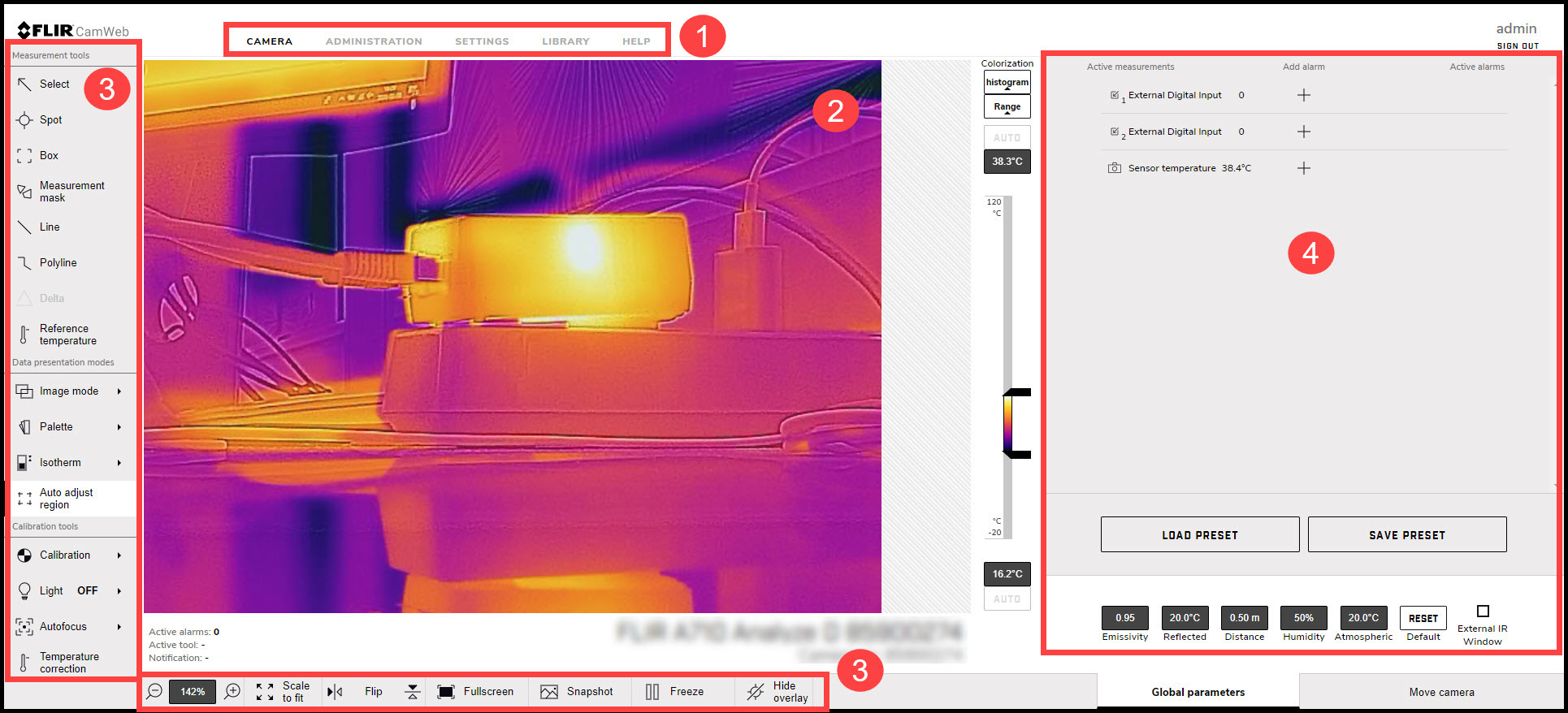
Figure 1. Camera web user interface
Tabs
Available tabs depend on user type;
An admin sees the Camera, Administration, Settings, and Library tabs.
A user sees the Camera, Settings, and Library tabs.
A viewer sees the Camera tab.
Live image
This is where the live image is presented of what the camera is currently targeting.
Toolbar
The toolbar options are grouped into the following categories;
Measurement tools
Data presentation modes
Calibration tools
View modes
-
Active measurements
Any measurement tools added to the image are displayed and managed from here.
Camera tab
The Camera tab is the default tab after logging in. Here it is possible to view the live image stream from the camera, make measurements, set alarms, take snapshots, calibrate the camera, manage image settings, etc.
Available functionality depends on the type of your FLIR camera; Image Streaming camera or Smart Sensor camera.
Working with measurement tools
To measure a temperature, you can use one or more measurement tools, e.g., a spot, a box, or a delta. The measurement tools are labeled with a number for identification, according to the order of their creation. Added measurement tools show up in the Active measurements section, where the they can be managed and where the measured temperatures are displayed.
Spot
A spot measurement tool shows the temperature of a specific spot in the image. It is possible to add up to ten spots.
To add a spot measurement tool, follow this procedure:
On the toolbar and in the Measurement tools section, click Spot.
In the image, click to insert the spot. The tool is labeled with a number, and it is also displayed in the Active measurements section.
To move the tool, click and hold the tool label in the image, and then move it into position.
To configure Settings for the tool, click
 next to the tool in the Active measurements section. This displays the Settings dialog box.
To change the label of the tool, change the Spot name.
To set local parameters for the tool, see section Local parameters.
To associate an alarm with the tool, see section Working with alarms.
To remove the tool, click Settings
next to the tool in the Active measurements section, and then click Delete measurement.
Box
A box measurement tool can show the minimum temperature, the maximum temperature, and the average temperature within a selected area of the image. It is possible to have up to ten boxes and masks at the same time.
To add a box measurement tool, follow this procedure:
On the toolbar and in the Measurement tools section, click Box.
In the image, click and then draw a box of a desired size. The tool is labeled with a number, and it is also displayed in the Active measurements section.
To move the tool, click and hold the tool label in the image, and then move it into position.
To resize the tool, click and hold one of the corners of the box in the image, and then move it to the desired size and shape.
To configure Settings for the tool, click
next to the tool in the Active measurements section. This displays the Settings dialog box.To change the label of the tool, change the Box name.
To select what measurement results to display, use the Maximum, Minimum, and Average check boxes.
Use the Local options to adjust the temperature scale according to the temperatures of the tool. For more information, see section Adjusting the temperature scale.
-
To display how much of the tool is covered by an isotherm, select the Iso check box. This setting is only applicable if you have selected a color alarm (isotherm). For more information, see section Isotherms.
To set local parameters for the tool, see section Local parameters.
To associate an alarm with the tool, see section Working with alarms.
To remove the tool, click Settings
next to the tool in the Active measurements section, and then click Delete measurement.
Measurement mask
Use the measurement mask tool to capture and measure more complex shapes in the image, for example the outlines of an electrical switch. It is possible to have up to ten masks and boxes at the same time. Note that one mask can contain one or several different shapes. However, only one Maximum, one Minimum, and one Average temperature will be displayed for the mask.
To add a measurement mask tool, follow this procedure:
On the toolbar and in the Measurement tools section, click Measurement mask.
In the image, click to insert the starting point of the mask. Move the pointer and click to insert the next point. Continue until you have the captured the desired shape. Finish by clicking the starting point. The tool is labeled with a number, and it is also displayed in the Active measurements section.
To configure Settings for the tool, click
next to the tool in the Active measurements section. This displays the Settings dialog box.To change the label of the tool, change the Mask name.
To select what measurement results to display, use the Maximum, Minimum, and Average check boxes.
Use the Local options to adjust the temperature scale according to the temperatures of the tool. For more information, see section Adjusting the temperature scale.
-
To display how much of the tool is covered by an isotherm, select the Iso check box. This setting is only applicable if you have selected a color alarm (isotherm). For more information, see section Isotherms.
To add another shape to the tool, click Draw and then draw the shape.
To set local parameters for the tool, see section Local parameters.
To associate an alarm with the tool, see section Working with alarms.
To remove the tool, click Settings
next to the tool in the Active measurements section, and then click Delete measurement.
Line
A line measurement tool shows the temperature along a specific line in the image. It is possible to add two lines.
To add a line measurement tool, follow this procedure:
On the toolbar and in the Measurement tools section, click Line.
In the image, click a starting point and then draw the line to the desired length. The tool is labeled with a number, and it is also displayed in the Active measurements section.
To move the tool, click and hold the tool label in the image, and then move it into position.
To change the length of the tool, click one of the end points, and then move it to the desired length.
To configure Settings for the tool, click
next to the tool in the Active measurements section. This displays the Settings dialog box.To change the label of the tool, change the Line name.
To select what measurement results to display, use the Maximum, Minimum, and Average check boxes.
Use the Local options to adjust the temperature scale according to the temperatures of the tool. For more information, see section Adjusting the temperature scale.
To set local parameters for the tool, see section Local parameters.
To add a temperature graph under the live image representing the tool, click the Display temperature graph check box.
To associate an alarm with the tool, see section Working with alarms.
To remove the tool, click Settings
next to the tool in the Active measurements section, and then click Delete measurement.
Polyline
A polyline measurement tool can show the minimum temperature, the maximum temperature, and the average temperature within a polyline drawn on the image. It is possible to add one polyline.
To add a polyline measurement tool, follow this procedure:
On the toolbar and in the Measurement tools section, click Polyline.
In the image, click to insert the starting point of the polyline. Move the pointer and click to insert the next point. Continue until you have the desired shape. Finish by clicking Confirm. The tool is labeled with a number, and it is also displayed in the Active measurements section.
To move the tool, click and hold the tool label in the image, and then move it into position.
To configure Settings for the tool, click
next to the tool in the Active measurements section. This displays the Settings dialog box.To change the label of the tool, change the Polyline name.
To select what measurement results to display, use the Maximum, Minimum, and Average check boxes.
Use the Local options to adjust the temperature scale according to the temperatures of the tool. For more information, see section Adjusting the temperature scale.
To set local parameters for the tool, see section Local parameters.
To add a temperature graph of the tool under the live image, click the Display temperature graph check box.
To associate an alarm with the tool, see section Working with alarms.
To remove the tool, click Settings
next to the tool in the Active measurements section, and then click Delete measurement.
Delta
Use the delta measurement tool to calculate the difference between two measurement results, or between a measurement result and a fixed temperature (reference temperature).
To add a delta measurement tool, follow this procedure:
On the toolbar and in the Measurement tools section, click Delta. The tool is displayed in the Active measurements section.
In the Active measurements section, click Settings
. The Delta settings dialog box appears.To change the label of the tool, change the Delta name.
In the Variable 1 and Variable 2 lists, select the measurement results you want to use in the calculation.
Click Save changes.
Reference temperature
The reference temperature can be used as a value which the measured values can be compared with.
To add a reference temperature, follow this procedure:
On the toolbar and in the Measurement tools section, click Reference temperature. The tool is displayed in the Active measurements section.
In the Active measurements section, click Settings
. The Reference temperature dialog
box appears.To change the label, change the Reftemp name.
In the Value box, type the temperature to be used as reference.
Click Save changes.
Working with alarms
You can make the camera trigger an alarm when certain conditions are met. An alarm can be triggered by several different sources, such as a measurement result in the image, a digital input, or an internal temperature sensor.
When an alarm is triggered, the camera can perform one or more tasks, e.g. save an image or video sequence to camera memory, or send the image/video by e-mail to predefined recipients or to an FTP site. The camera can also further trigger a variety of external devices, using the digital output.
All active alarms are listed in the Active alarms section. A triggered alarm turns red in the Active alarms section. Also, the label of the measurement tool in the image turns red.
Setting an alarm based on a measurement result
To configure an alarm based on the measurement result from a spot, box, or delta measurement tool, follow this procedure:
In the Active Measurements section, click the plus sign under Add alarm next to the measurement result to be used for the alarm. The Add alarm dialog box appears.
In the Alarm label section, type an Alarm name.
In the Trigger section, select the Condition and temperatures that will trigger this alarm:
-
Below
-
Triggers an alarm when the temperature is below the specified Threshold value. Also type a Hysteresis value.
-
Above
-
Triggers an alarm when the temperature is above the specified Threshold value. Also type a Hysteresis value.
-
Interval
-
Triggers an alarm when the temperature is within the specified Min value and Max value.
Hysteresis is the interval within which the temperature value is allowed to vary without causing a change in the trigger. If the threshold is set above 30.0°C and the hysteresis is set at 2.0°C, the trigger goes high when the temperature rises above 30.0°C and stays high until the temperature drops below 28.0°C. In contrast, if the threshold is set below 30.0°C, and the same hysteresis value is kept, the trigger goes high if the temperature drops below 30.0°C and stays high until the temperature rises above 32.0°C.
-
In the Threshold time box, type the amount of time that has to pass before an alarm is triggered. This can be used to avoid false alarms.
In the Action section, select which actions the camera will perform when an alarm is triggered:
-
Digital OUT
-
Outputs a digital pulse. Also, type a pulse length (in milliseconds) in the Pulse time box.
-
E-mail
-
Automatically sends the captured Image, Result, or Video to the recipients defined in Settings > Alarm recipients. For more information, see section Alarm recipients.
-
Send to FTP
-
Automatically sends the captured Image or Video to the FTP site defined in Settings > Alarm recipients. For more information, see section Alarm recipients.
-
Save to camera
-
Automatically saves the captured Image or Video to the memory of the camera.
-
During alarm
-
Temporarily disables the periodic calibration while the image/video is being captured.
The image/video can later be viewed and managed under the Library tab:
the captured image frame that triggered the alarm,
the 5 second video sequence when the alarm was triggered.
-
When completed, click Set alarm. The alarm is now listed under Active alarms.
Setting an alarm based on the digital input
To configure an alarm based on the digital input, follow this procedure:
In the Active Measurements section, click the plus sign under Add alarm next to the digital input result to be used for the alarm. The Alarm dialog box appears.
In the Alarm label section, type an Alarm name.
In the Trigger section and in the Value list; select “0” to trigger the alarm on a low signal or select “1” to trigger on a high signal.
In the Action section, select which actions the camera will perform when an alarm is triggered:
-
Digital OUT
-
Outputs a digital pulse. Also, type a pulse length (in milliseconds) in the Pulse time box.
-
E-mail
-
Automatically sends the captured Image, Result, or Video to the recipients defined in Settings > Alarm recipients. For more information, see section Alarm recipients.
-
Send to FTP
-
Automatically sends the captured Image or Video to the FTP site defined in Settings > Alarm recipients. For more information, see section Alarm recipients.
-
Save to camera
-
Automatically saves the captured Image or Video to the memory of the camera.
-
During alarm
-
Temporarily disables the periodic calibration while the image/video is being captured.
The image/video can later be viewed and managed under the Library tab:
the captured image frame that triggered the alarm,
the 5 second video sequence when the alarm was triggered.
-
When completed, click Set alarm. The alarm is now listed under Active alarms.
Setting an alarm based on sensor temperature
The internal temperature sensor can act as a thermometer for the ambient temperature. To configure an alarm based on the internal temperature sensor, follow this procedure:
In the Active Measurements section, click the plus sign under Add alarm next to the Sensor temperature. The Alarm dialog box appears.
In the Alarm label section, type an Alarm name.
In the Trigger section, select the Condition and temperatures that will trigger this alarm:
-
Below
-
Triggers an alarm when the temperature is below the specified Threshold value. Also type a Hysteresis value.
-
Above
-
Triggers an alarm when the temperature is above the specified Threshold value. Also type a Hysteresis value.
-
Interval
-
Triggers an alarm when the temperature is within the specified Min value and Max value.
Hysteresis is the interval within which the temperature value is allowed to vary without causing a change in the trigger. If the threshold is set above 30.0°C and the hysteresis is set at 2.0°C, the trigger goes high when the temperature rises above 30.0°C and stays high until the temperature drops below 28.0°C. In contrast, if the threshold is set below 30.0°C, and the same hysteresis value is kept, the trigger goes high if the temperature drops below 30.0°C and stays high until the temperature rises above 32.0°C.
-
In the Threshold time box, type the amount of time that has to pass before an alarm is triggered. This can be used to avoid false alarms.
In the Action section, select which actions the camera will perform when an alarm is triggered:
-
Digital OUT
-
Outputs a digital pulse. Also, type a pulse length (in milliseconds) in the Pulse time box.
-
E-mail
-
Automatically sends the captured Image, Result, or Video to the recipients defined in Settings > Alarm recipients. For more information, see section Alarm recipients.
-
Send to FTP
-
Automatically sends the captured Image or Video to the FTP site defined in Settings > Alarm recipients. For more information, see section Alarm recipients.
-
Save to camera
-
Automatically saves the captured Image or Video to the memory of the camera.
-
During alarm
-
Temporarily disables the periodic calibration while the image/video is being captured.
The image/video can later be viewed and managed under the Library tab:
the captured image frame that triggered the alarm,
the 5 second video sequence when the alarm was triggered.
-
When completed, click Set alarm. The alarm is now listed under Active alarms.
Changing object parameters
For accurate measurements, the camera must be provided with certain object parameters:
Emissivity
How much radiation an object emits, compared with the radiation of a theoretical reference object at the same temperature (called a “blackbody”). The opposite of emissivity is reflectivity. The emissivity determines how much of the radiation originates from the object as opposed to being reflected by it.
Reflected temperature
This is used when compensating for the radiation from the surroundings reflected by the object into the camera. This property of the object is called reflectivity.
Distance
The distance between the camera and the object of interest.
Relative humidity
The relative humidity of the air between the camera and the object of interest.
Atmospheric temperature
The temperature of the air between the camera and the object of interest.
External IR window
Used if any protective windows etc. are set up between the camera and the object of interest. When the setting is on, the following parameters can be set:
Transmission: How much of the thermal radiation passes through the window.
Temperature: The temperature of the window.
You can set the object parameters globally. You can also change the Emissivity, Reflected temperature, and Distance parameters locally for a measurement tool.
The local parameter settings override the global values.
Of the object parameters, Emissivity and Reflected temperature are the two most important to set correctly in the camera.
Global parameters
The global parameters are shown in the bottom right corner of the screen, below the Active measurements section.
To change the global parameters, follow this procedure:
In the bottom right corner of the screen, click to select the parameter to change.
Change the parameter to the desired value, and then press Enter or click anywhere on the screen.
To reset the global parameters to the default values provided by FLIR, click Reset.
Local parameters
The local parameter settings override the global values. To change the local parameters, follow this procedure:
In the Active measurements section, click Settings
next to the tool for which you want to change the parameters. The Settings dialog box appears.To activate the use of local parameters, select the Local parameters check box. The values for the Emissivity, Reflected temperature, and Distance parameters are now editable.
To deactivate the use of local parameters, deselect the Local parameters check box.
When completed, click Save changes.
Working with image modes
The camera captures both thermal and visual images at the same time. By your choice of image mode, you select which type of image to display on the screen.
The camera supports the following image modes:
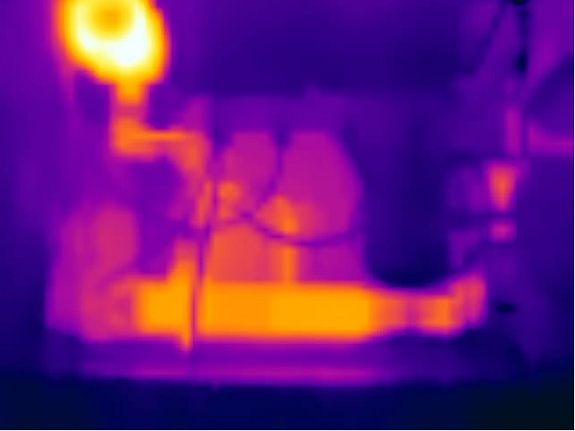
Thermal: The camera displays a fully thermal image.
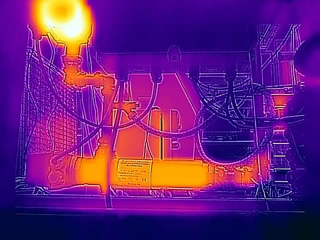
MSX (Multi Spectral Dynamic Imaging): The camera displays the thermal image where details from the visual image have been added.
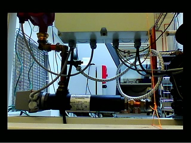
Visual: The camera displays the visual image captured by the visual camera.
-
FSX (Flexible Scene Enhancement): The camera displays the thermal image with enhanced image details. This image mode is useful when higher contrast is required, for example when the camera is used in a surveillance application.
The availability of the visual camera depends on the lens model. When the visual camera is disabled, only the image modes Thermal and FSX are available.
To select the image mode, follow this procedure:
On the toolbar and in the Data presentation modes section, click Image mode.
Select one of the available image modes.
Colorizing the image
The camera can colorize the image in different ways. You can select different color palettes or apply color alarms (isotherms).
Palette
You can change the palette that the software uses to display the different temperatures within an image. A different palette can make it easier to analyze the image. The most suitable palette for a certain application depends on many different factors, such as the target temperature and emissivity, the ambient temperature, and the distance to the target. You will need to test different palettes in order to find the one that best suits your application.
To change the palette, follow this procedure:
On the toolbar and in the Data presentation modes, click Palette.
Select one of the available palettes.
Isotherms
By using color alarms (isotherms), anomalies can easily be discovered in an infrared image. The isotherm command applies a contrasting color to all pixels with a temperature above, below, or between the set temperature levels.
The camera supports the following isotherms:
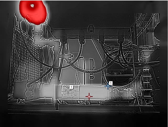
Above
Applies a contrasting color (red) to all pixels with a temperature above the specified temperature level.
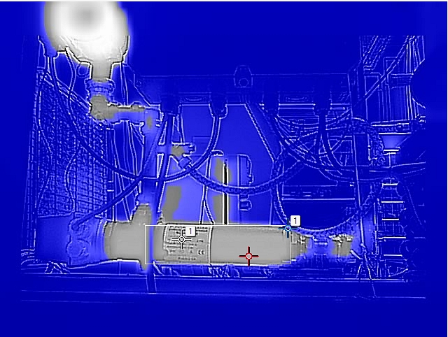
Below
Applies a contrasting color (blue) to all pixels with a temperature below the specified temperature level.
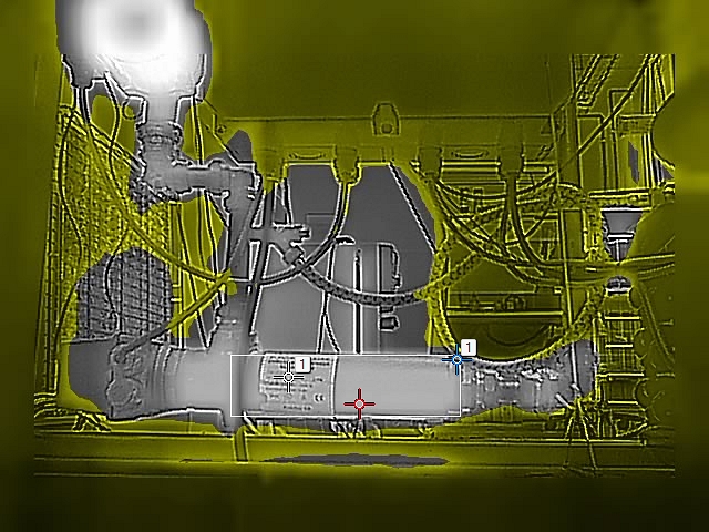
Interval
Applies a contrasting color (yellow) to all pixels with a temperature between two specified temperature levels.
To configure an isotherm, follow this procedure:
On the toolbar and in the Data presentation modes section, click Isotherm.
Select one of the available isotherms.
When a color alarm is selected, it is displayed in the Active measurements section. Also, a temperature indicator is added to the left side of the temperature scale located to the right of the image.
To change the threshold temperature, click Settings
next to the isotherm in the Active measurements section. The Settings dialog box appears.In the Range section, set the threshold temperature of the isotherm:
Above; type a threshold temperature in the From box.
Below; type a threshold temperature in the To box.
Interval; type the interval temperatures in the To and From boxes.
Optionally, change the contrasting color in the Highlight color section.
When completed, click Save changes.
Auto-adjust region
By using the Auto-adjust region feature it is possible to select an area of the image, and then have the colorization of the image adjusted based on the temperatures within that selected area.
To configure an auto-adjust region, follow this procedure:
On the toolbar and in the Data presentation modes section, click Auto-adjust region.
In the image, click and then draw a region of a desired size.
To move the region, click and hold the region label in the image, and then move it into position.
To resize the region, click and hold one of the corners of the region in the image, and then move it to the desired size and shape.
To remove the region, click X in the region label.
Calibrating the camera
The calibration of the camera is performed as a non-uniformity correction (NUC). A NUC is an image correction carried out by the camera software to compensate for different sensitivities of detector elements and other optical and geometrical disturbances1.
Calibration is needed whenever the output image becomes spatially noisy. This may, for example, happen when the ambient temperature changes. The calibration can be carried out automatically with different selectable intervals. It is also possible to perform a calibration manually.
Automatic calibration
To set the automatic calibration, follow this procedure:
On the toolbar and in the Calibration tools section, click Calibration. This displays a list of calibration options.
Click one of the options:
-
Option
-
Calibration is automatically carried out:
-
Auto
-
when needed.
-
Every 10 min
-
approximately every 10 minutes, or when needed.
-
Every 30 min
-
approximately every 30 minutes, or when needed.
-
Every 60 min
-
approximately every 60 minutes, or when needed.
-
Every [type your value]
-
at any set interval.
-
OFF
-
never (automatic calibration disabled).
-
While the automatic calibration is in progress, the Notification text Calibration in progress ... is temporarily displayed under the live image.
Manual calibration
To perform a manual calibration, follow this procedure:
On the toolbar and in the Calibration tools section, click Calibration. This displays a list of calibration options.
Click Calibrate now.
While the manual calibration is in progress, the Notification text Calibration in progress ... is temporarily displayed under the image on the screen
MSX alignment
For correct alignment of the thermal and visual images, the camera needs input on the distance to the objects of interest. Note that this is only required for the FLIR A40/A50/A70 cameras with 29° and 51° lenses, since MSX is not supported by cameras with 95° lenses.
Changing the temperature range
For accurate measurements, it is recommended to use the temperature range closest to the temperature of the object being monitored. For example, if the hottest object in the scene is 87°C, the temperature range “-20°C to 120°C” should be used.
The temperature range is visible to the right of the live image. Click Range and select a suitable range from the list.
For Image Streaming cameras, the temperature range can also be changed over GenICam.
Adjusting the temperature scale
The camera continuously auto-adjusts the image for the best image brightness and contrast. In some situations, manual adjustments can make it easier to analyze details in the image. For example, by manually changing the maximum and/or minimum temperature levels to levels near a certain object in the image, you can study temperature variations in the object.
The temperature scale is visible to the right of the live image. When a temperature level is manually adjusted, the Auto button is displayed next to the temperature scale box.
To manually adjust the image, follow this procedure:
To change the maximum temperature level, type the temperature in the upper temperature scale box. As an alternative, click and hold the upper temperature bar on the scale, and then move it into position. Watch the temperature in the scale box change as you move the bar.
To change the minimum temperature level, type the temperature in the lower temperature scale box.As an alternative, click and hold the lower temperature bar on the scale, and then move it into position. Watch the temperature in the scale box change as you move the bar.
To return to auto-adjustment, click the Auto button(s).
Flipping the image
The image can be flipped horizontally or vertically.
|
Normal 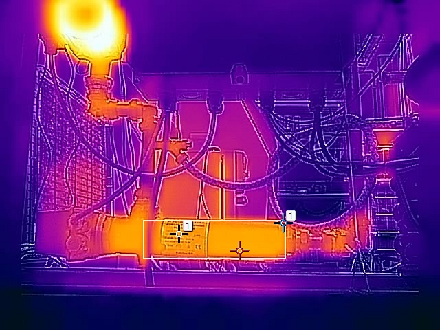 |
Horizontal flip 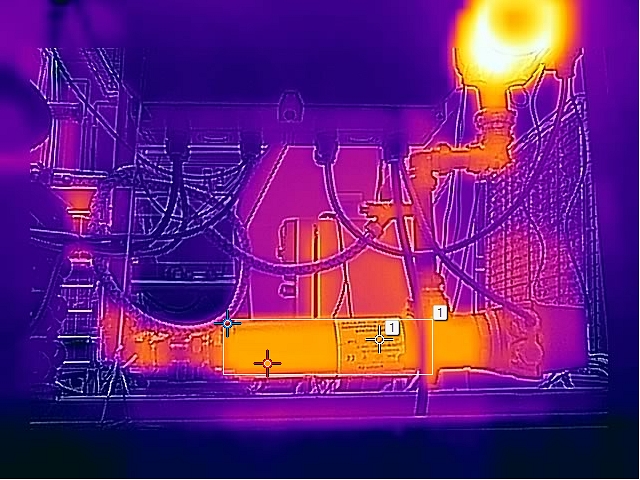 |
|
Vertical flip 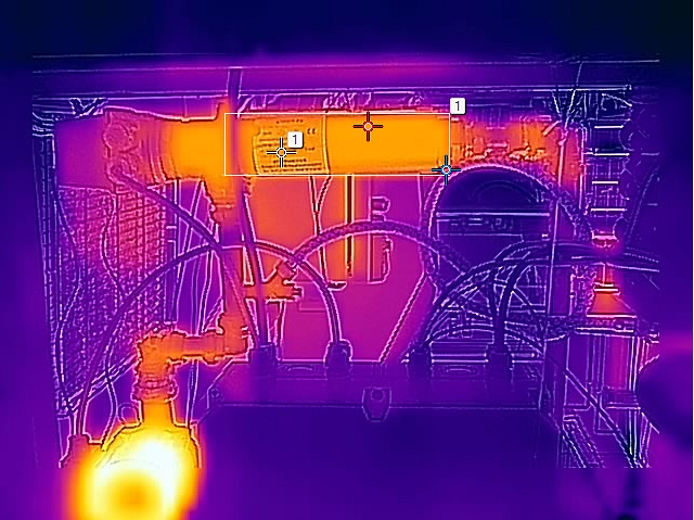 |
Horizontal + vertical flip 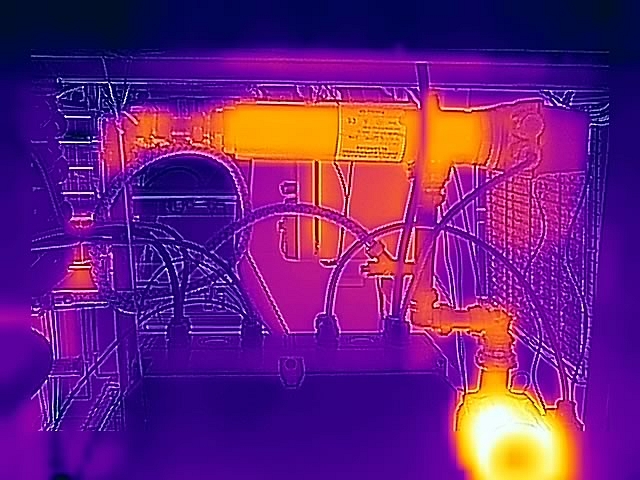 |
To change the flip setting, follow this procedure:
On the toolbar and in the View modes section, click
 to flip the image horizontally or click
  to flip the image vertically.
Full screen view
To view the image in full screen, follow this procedure:
On the toolbar and in the View modes section, click Full screen.
To return to normal view, press the Esc (Escape) key on the computer keyboard.
Saving a snapshot
It is possible to take a snapshot and save the image with the current measurement results. The image can later be viewed and managed on the Library tab. Up to 100 images can be saved.
To take a snapshot, follow this procedure:
On the toolbar and in the View modes section, click Snapshot.
The Notification text Snapshot stored is temporarily displayed under the live image.
Pausing the live image stream
To pause or freeze the live image stream, follow this procedure:
On the toolbar and in the View modes section, click Freeze.
To resume the live image stream, click Unfreeze.
Hiding the overlay graphics
To hide all overlay graphics in the live image, follow this procedure:
On the toolbar and in the View modes section, click Hide overlay.
To show any hidden overlay graphics, click Show overlay.
Filter levels
The filter level affects how much the raw image is filtered before it is presented to the user. Depending on the scene, the filters can provide a better image quality. Different applications might benefit from different filters, and it is recommended to try the available filter levels for each application. The measurement accuracy is not affected by the filters.
Camera presets
It is possible to save the current camera setup, including measurement tool configurations, alarms, and colorization settings. The zipped file with the presets is saved to disk in your Downloads folder. It can later on be uploaded and applied.
Saving a preset
To save the current camera setup, follow this procedure:
In the Active measurements section, click Save preset.
Loading a preset
To load a saved preset file, follow this procedure:
In the Active measurements section, click Load preset. The standard Windows Open dialog box appears.
Browse to the Downloads folder (or to the folder where you have stored the preset files).
Select the file, and then click Open. This loads and applies the presets.
Administration tab
The Administration tab is only available for the admin role.
Under the Administration tab you can for example, manage firewall and network settings and see system and firmware details.
Firewall
Use the settings on the Firewall page to configure how the functions and services of the camera are allowed to be accessed.
The services also need to be enabled which is done on the Services page.
SSL certificates
A network client program that is setup to communicate with or control the camera remotely must be approved first, which is done on the SSL certificates page. The client uploads a certificate which is then shown in the Certificates list, and then the camera administrator can approve the client. Approved clients can be revoked later on.
Temporarily enable the Auto approve functionality while setting up the network clients. However, it is recommended to disable Auto approve when all setup is completed.
Services
Use the Services page to enable and disable the services of the camera.
Available services:
Ethernet/IPEnable this service when the camera is to communicate using industrial protocols such as Modbus TCP and Ethernet/IP. The camera can be used as either a Modbus client or a Modbus server. The settings for the Modbus client are located under the Settings tab. If the camera should be used as a Modbus server, the registers can be downloaded from the FLIR Customer support site.
Pantilt serverEnable this service when the camera is connected to a Pan & Tilt unit. If the camera is connected to the unit using an RS-232/485 interface, it can control the unit from the Camera tab or by using ONVIF.
httpResourceThe httpResource service is an old way of controlling the camera. It should only be enabled if legacy FLIR software is used.
ONVIFEnable this service when the camera is to communicate with Video Management Systems (VMS) over ONVIF. If the service is disabled, the camera will not be discovered by third-party VMS. Note that the Advanced configuration is required on the camera for ONVIF to work.After enabling the service, also click Apply to initialize it. When enabled, settings for the ONVIF users can be managed.
ONVIF usersThis section controls the ONVIF users and credentials, and it is only accessible if the ONVIF service is active.Default credentials are; user name = fliruser and password = 3vlig.
The services also need to be allowed to be accessed which is done on the Firewall page.
Web protocols
Use the Web protocols page to configure which web protocol to use when accessing the camera; http or https.
User management
Use the User management page to enable and disable user roles, and to change passwords.
The viewer and user roles are disabled by default.
A hard factory reset of the camera will reset the administrator password to the default password. See Indicator LEDs and factory reset button.
Regional settings
Use the Regional settings page to set Date and time and preferred Units.
Date and time can be set in four ways:
Get date and time from an SNTP Server (Simple Network Time Protocol):
Select the Enable check box, and then type the IP address of the SNTP Server in the Server address box.
Set date and time manually:
Select the correct Time zone in the list, and then type date and time information in the Year, Month, Day, Hour, Minute, and Second boxes.
Get date and time from your internet browser:
Click Read from browser.
Get date and time from your camera:
Click Read from camera.
Available Units are:
Celsius (C) and Fahrenheit (F)
Meter (m) and Foot (ft)
Network settings
Use the Network settings page to manage the network setup and to select the streaming bit rate.
When altering the network settings, the address of the camera might change. Make sure your settings are correct before saving them or the camera might not be reachable afterwards. If this occurs, you can use FLIR IP Config to locate the camera again or reset the camera to its default settings.
Ethernet setup
Follow this procedure:
In the navigation pane, click Network settings.
Select one of the following:
To automatically obtain an IP address for the camera, click Obtain IP address automatically (DHCP).
To manually set an IP address for the camera, click Manual configuration, and then type valid network information in the IP, Subnet mask, and Gateway boxes.
Click Apply.
Wireless
The Wireless connection can be set to Off, Server mode, or Client mode.
In Server mode, you configure the camera itself to act as a wireless server allowing other devices to connect, such as mobile phones or tablets. This is useful in situations where no other network exists. In Client mode you connect the camera to an existing network.
To let the camera act as a wireless server, follow this procedure:
In the navigation pane, click Network settings.
Click Server mode.
Type a Network name and a Password for accessing the network.
Click Share network.The camera will now act as a “hotspot” that computers or tablets (with high resolution) can connect to. When a wireless connection has been established, the camera will be available at the IP address 192.168.16.1.
To connect the camera to an existing network, follow this procedure:
In the navigation pane, click Network settings.
Click Client mode.
Click Scan networks.
Select one of the Available networks in the list, and then click Connect.
Type the Password for accessing the network, and then click Connect.
Streaming bit rate
Follow this procedure:
In the navigation pane, click Network settings.
In the Streaming bit rate list, select one of the available bit rates.
Click Apply.
System and firmware
The System and firmware page displays System version, Software details, and Hardware details of the camera. In the System section, you can restart the camera, reset the camera to factory settings, or upgrade the camera firmware.
Restart camera
Follow this procedure:
In the navigation pane, click System and firmware.
In the System section, click Restart camera. This displays a dialog box.
In the dialog box, click OK. The camera will restart.
Reset camera to factory settings
A factory reset will affect all camera settings, including regional settings. Saved images will not be affected.
Follow this procedure:
In the navigation pane, click System and firmware.
In the System section, click Reset to factory settings. This displays a dialog box.
In the dialog box, click OK. The camera will restart.
Upgrade camera firmware
Follow this procedure:
In the navigation pane, click System and firmware.
In the System section, click Upgrade firmware. This displays a dialog box.
Click Select file. The standard Windows Open dialog box appears.
Browse to the location of the firmware file, select the file, and then click Open.
Click Upgrade firmware.
When the upgrade is completed, restart the camera.
SNMP settings
Use the SNMP settings page to enable and disable Simple Network Management Protocol (SNMP). When enabled, type the IP address of your device, and the port and interval time.
Sink: The IP address to send trap messages to (trap receiver).
Port number: Destination port used for trap (default port number is 162).
Interval: An integer value (in seconds) between the heartbeat signals.
Multicast settings
Use the Multicast settings page to manage the settings for multicast communication, which can be used when multiple clients are using the camera video stream. Settings can be changed for each of the two video streams; IR and Visual/Digital Camera.
Settings tab
The Settings tab is only available for the admin and user roles.
Under the Settings tab you can manage:
General settings
Alarm recipients
Scheduler
MQTT
Modbus
General settings
The General settings page displays Product information, Camera ID, IP6x settings, and the possibility to Test Digital Input/Output functionality.
Camera ID
Type the preferred camera ID in the Device label box. Select the Display in status bar check box to show the camera ID on the active tab of the web browser and in the upper part of saved images.
Test Digital Input/Output
Use the test buttons to the test the electrical interfaces of the camera and the communication with them. These tests are useful when you set up the interfaces.
Click Test (5s). A successful test is indicated by a green “dot” for 5 seconds.
Alarm recipients
Use the Alarm recipients page to configure alarm notifications. Notifications can be sent by e-mail or to a folder on an FTP server.
To configure delivery by e-mail, follow this procedure:
In the navigation pane, click Alarm recipients.
In the Alarm recipient e-mail box, type the e-mail address of the recipient.
In the Mail server setup box, type the IP address of the sending mail server.
If the sending mail server requires a login (mail server authentication), select the Authentication required check box, and then type the credentials in the User and Password boxes.
Click Apply.
To configure delivery to FTP, follow this procedure:
In the navigation pane, click Alarm recipients.
In the FTP Server IP address box, type the IP address of the FTP server.
In the Folder box, type the path to the folder where you want to save the notifications. This can be useful if you have multiple cameras connected to the same FTP server.
In the User and Password boxes, type the credentials for FTP access.
Click Apply.
Scheduler
Use the Scheduler page to configure what actions to run, and when to run them. The result of an action can be sent by e-mail or to a folder on an FTP server.
Available actions are:
E-mail image
Send the image with overlay graphics.
-
E-mail result
Send a list of the active measurements and their respective temperatures.
Save image on FTP
Send the image with overlay graphics to an FTP server.
To schedule actions, follow this procedure:
In the navigation pane, click Scheduler.
Click the check boxes to select which Scheduled actions to use.
In the schedule, click the Active check box for the days that the action will run:
To run the action once a day at a certain time, also click Once and then set an Action Time.
To run the action several times a day, also click Repeat and then set a time Interval, a Start action time, and an End action time.
Click Apply.
To configure delivery to FTP, follow this procedure:
In the FTP Server box, type the IP address of the FTP server.
In the FTP User and FTP Password boxes, type the credentials for the FTP access.
Click Apply.
To configure delivery by e-mail, follow this procedure:
In the Recipient e-mail box, type the e-mail address of the recipient.
In the Mail server box, type the IP address of the sending mail server.
In the Sender e-mail box, type the e-mail address of the sender.
If the sending mail server requires a login (mail server authentication), select the Authenticate mail check box, and then type the credentials in the User and Password boxes.
Click Apply.
MQTT
It is possible to setup a publish/subscribe messaging transport using the MQTT protocol (MQ Telemetry Transport). Topics that are available for subscription are shown in the Topic subscriptions section. Note that the corresponding measurement functions and alarms must be defined and active, or no information will be published.
Follow this procedure:
In the navigation pane, click MQTT.
Click the Enable MQTT check box.
Type the Broker host address and the TCP Broker Port used for the subscription transport.
Type the User and Password to login to the broker.
Select preferred Temperature unit in the list; Celsius (C), Fahrenheit (F), or Kelvin (K).
Select preferred Output format in the list; Json or Text.
Click Apply.
In your MQTT client of choice, set up a subscription for the topic corresponding to the information of interest. The topics will be updated when the data is updated, for example; if you subscribe to the topic FLIR/ec501-xxxxxx/alarm1, your MQTT client will receive an update when alarm1 is triggered and then another update when alarm1 criteria are no longer fulfilled. You can connect multiple cameras to the same MQTT broker.
Modbus
Use the Modbus page to configure remote transport of alarms and measurements.
Digital out
The camera has two digital outputs which can be used for remote transport of alarms. By using a Modbus controlled digital out box installed on the network it is possible to get another 10 “soft” digital outputs. In this setup the camera will act as Modbus master controlling the digital out box acting as Modbus slave.
To configure a digital out, follow this procedure:
In the navigation pane, click Modbus.
In the Digital out list, click Configure for the digital out number you want to use.
In the Digital output entry dialog box, type a Name of the entry. Also, type the IP Address, Device function ID, and Modbus Register address specific to the equipment.
Select Type specific to the equipment.
Click Apply.
To test the Modbus output, click Test which will activate the output for 5 seconds.
The digital out is now selectable in the Digital Out list when setting up alarms, see section Working with alarms.
Analogue out
The camera has no analogue outputs, but by using the built-in Modbus master functionality and an analogue out box controlled over Modbus, 10 individual analogue outputs become available. By selecting the corresponding analogue output box, volt or ampere representation of a measured value is possible.
To configure an analogue out, follow this procedure:
In the navigation pane, click Modbus.
In the Analogue out list, click Configure for the analogue out number you want to use.
In the Analogue output entry dialog box, type a Name of the entry.
Type the following information:
Select which Measurement function and Update interval (ms) to use. The Update interval (ms) defines how often a new value is sent over Modbus to the external analogue output box.
Type the IP Address, Device function ID, and Modbus Register address specific to the equipment.
Select Type specific to the equipment.
Type the Minimum temperature and the Maximum temperature to be represented.
In the Data output at Minimum temperature and Data output at Maximum temperature boxes, type the digital values to be sent over Modbus representing the Minimum temperature and Maximum temperature, respectively.
NoteThe data output depends on the analogue box being used. If the box supports an analogue output of 0 to 20 mA with the resolution 12-bit, the minimum data output will be 0 and the maximum will be 4095.
Click Apply.
To test the Modbus output, click Test which will activate the output for 5 seconds.
Library tab
The Library tab is only available for the admin and user roles.
Under the Library tab you can view and manage saved images and videos from alarms and snapshots. When downloading multiple images or videos, a pop-up window will appear. Make sure it is not blocked by your internet browser.
Managing images
To view and manage image files, follow this procedure:
In the navigation pane, click Images.
To display a preview of an image, click the thumbnail of the image.As an alternative, click the image file name, and then click Preview.
To download an image, click the image file name, and then click Download.
To delete one or more images, click the image file name(s), and then click Delete.
Managing videos
To manage video files, follow this procedure:
In the navigation pane, click Videos.
To download a video, click the video file name, and then click Download.
To delete one or more videos, click the video file name(s), and then click Delete.
Managing logs
The alarms can be logged to file. To manage log files, follow this procedure:
In the navigation pane, click Logs.
To enable logging of alarms, click the Logging enabled check box.
To download the generated logs as a zipped file, click Download log.
To delete the generated logs, click Clean log.