Camera user interface
iXX
This chapter describes the user interface for the iXX camera.
Screen elements
General
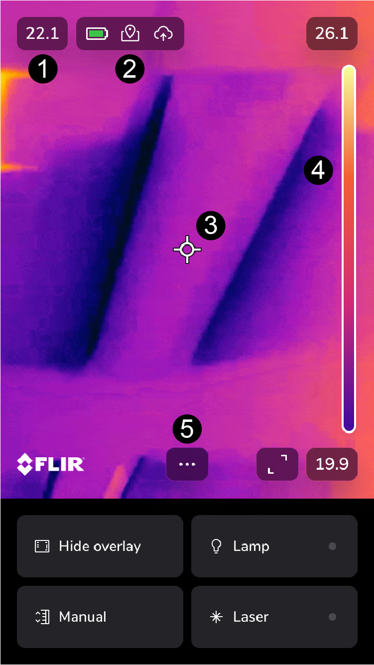
Result table
Status icons and indicators
Spotmeter
Temperature scale
Menu button
Full screen
Status icons and indicators
 |
Battery level
|
 |
Charging |
 |
The available storage space in the camera memory is running low. |
 |
GPS |
 |
Connected with a cloud account |
Main toolbar
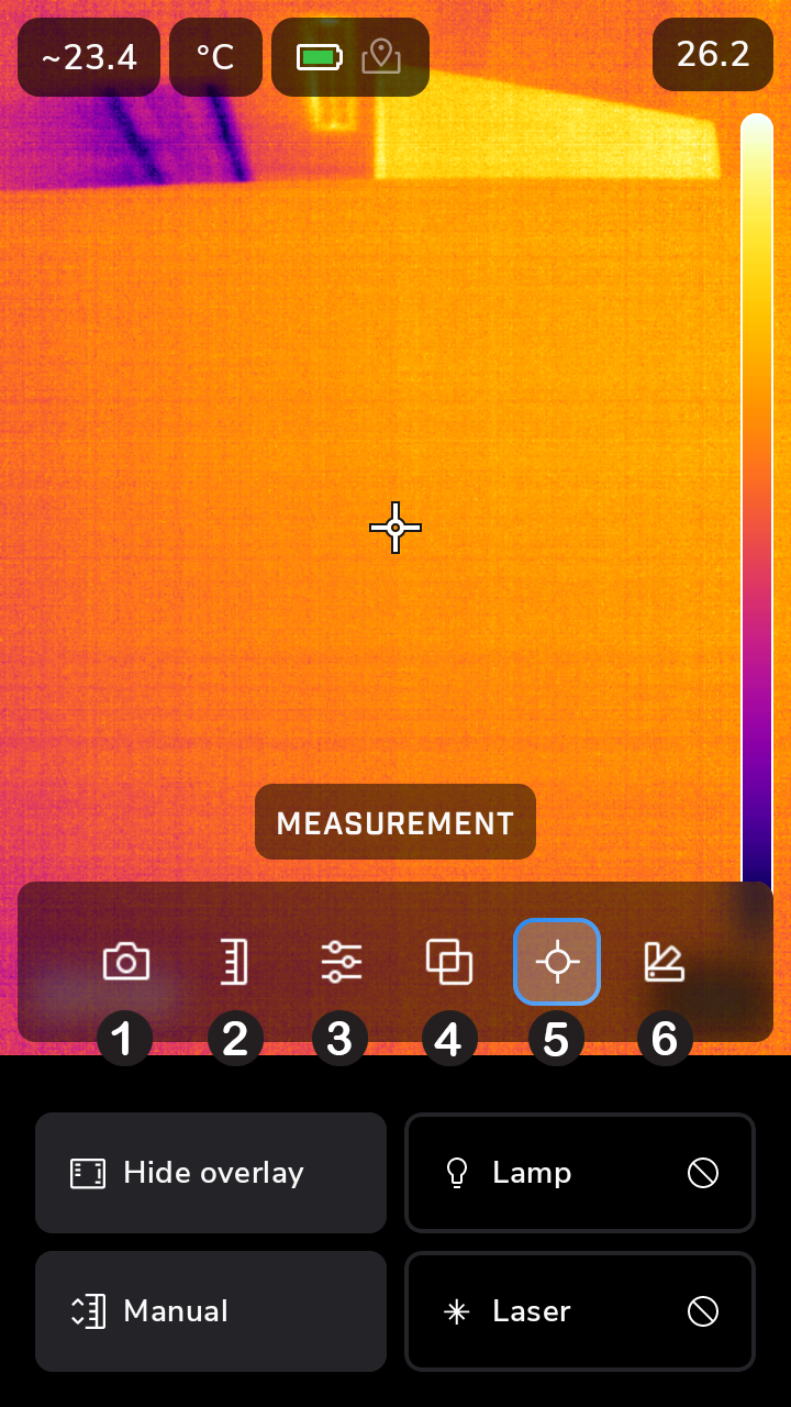
Recording mode: still image/video
Image adjustment: auto/manual
Parameters
Camera mode
Measurement
Color
Navigation keypad
To navigate the user interface, use the touch screen and/or the navigation keypad and Back button.
To display the main toolbar, push the three dots or the center of the navigation keypad.
To navigate the toolbars, menus, and dialog boxes, and to change values in dialog boxes, tap the navigation keypad up/down or left/right.
To confirm changes and settings in menus and dialog boxes, push the center of the navigation keypad or on the screen outside the toolbar.
To leave the dialog boxes and to go back in the menu system, push the Back button or tap the center of the navigation pad.
Image modes
The camera can capture thermal and visual images at the same time. In image mode, select which type of image to display on the screen.
The camera supports the following image modes:
Thermal MSX (Multi Spectral Dynamic Imaging): An infrared image where the edges of the objects are enhanced with visual image details.
Thermal: An infrared image.
Picture in picture: An infrared image frame is displayed on top of the visual image.
Digital camera: The visual image captured by the digital camera.
For the Thermal MSX, Thermal, and Picture in picture modes, all thermal and visual information is stored when an image is saved. This means that you can edit the image later, in the camera image library or in a Flir Thermography software, and select any of the image modes.
For the Digital camera image mode, a digital image with full resolution is stored when an image is saved. However, no thermal information is stored.
The following images are only sample images, they were not taken with an iXX camera.
Thermal MSX |
Thermal |
Picture in picture |
Digital camera |
Change image mode
On the main toolbar, select Image mode.
A new toolbar will show.
Select an image mode.
Align the thermal and visual images
In Thermal MSX and Picture in picture modes, the camera displays a combination of thermal and visual images.
To align the thermal and visual images, do the following:
Tap the distance indicator at the top of the screen.
Move the slider to align the images.
T5xx, T8xx, Exx
This chapter describes the user interface for the T5xx, T8xx, and Exx cameras.
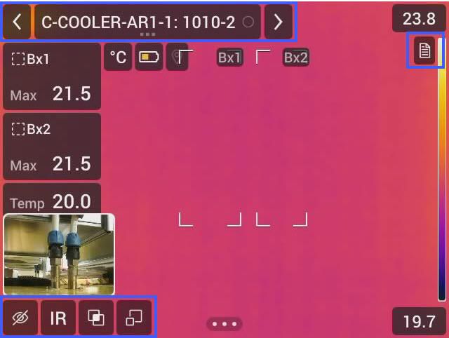
Figure 1.
Back arrow
Click to go to the previous inspection point.
Current point indicator
Shows the name of the current inspection point.
Shows an image icon if there is an image saved for the inspection point.
Shows the status of the inspection point.
Next arrow
Click to go to the next inspection point.
Document icon
This icon is shown if there is a description and/or comment available for the inspection point. A description comes from the route file and can, for example, include instructions or reminders for the inspection point. Comments are text notes added during the inspection. Click on the icon to show the description and/or comment.
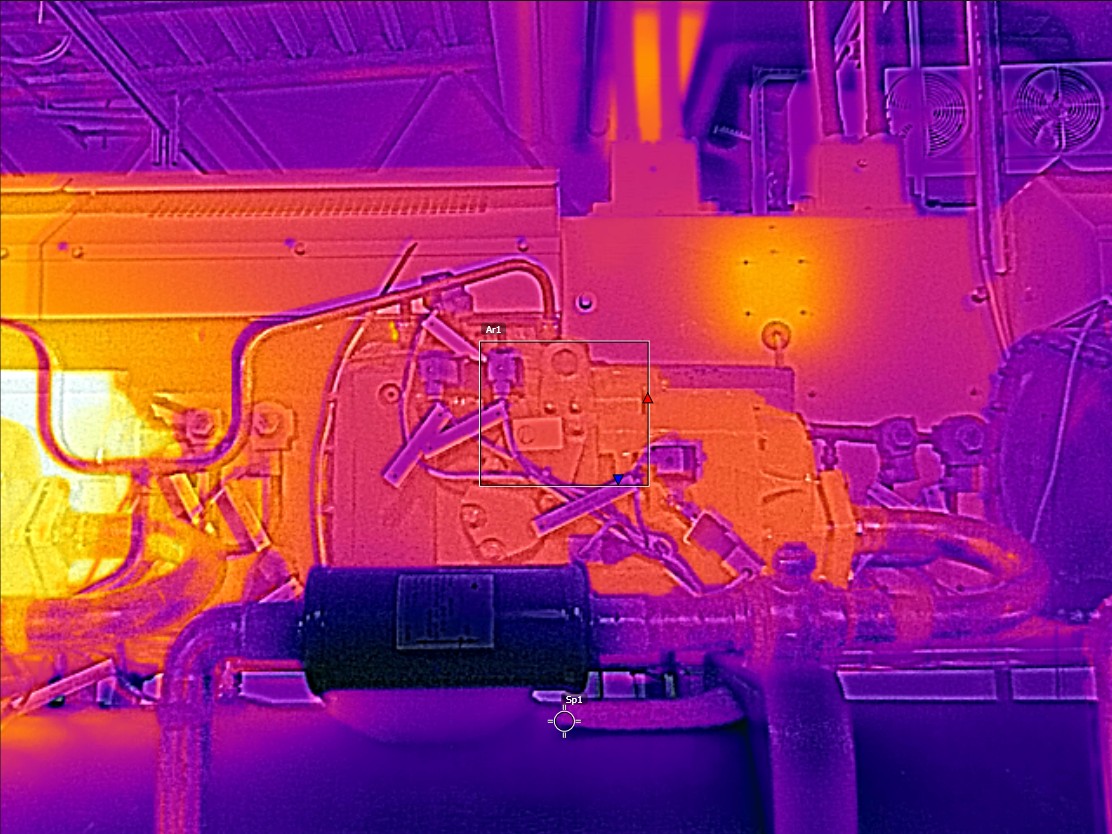
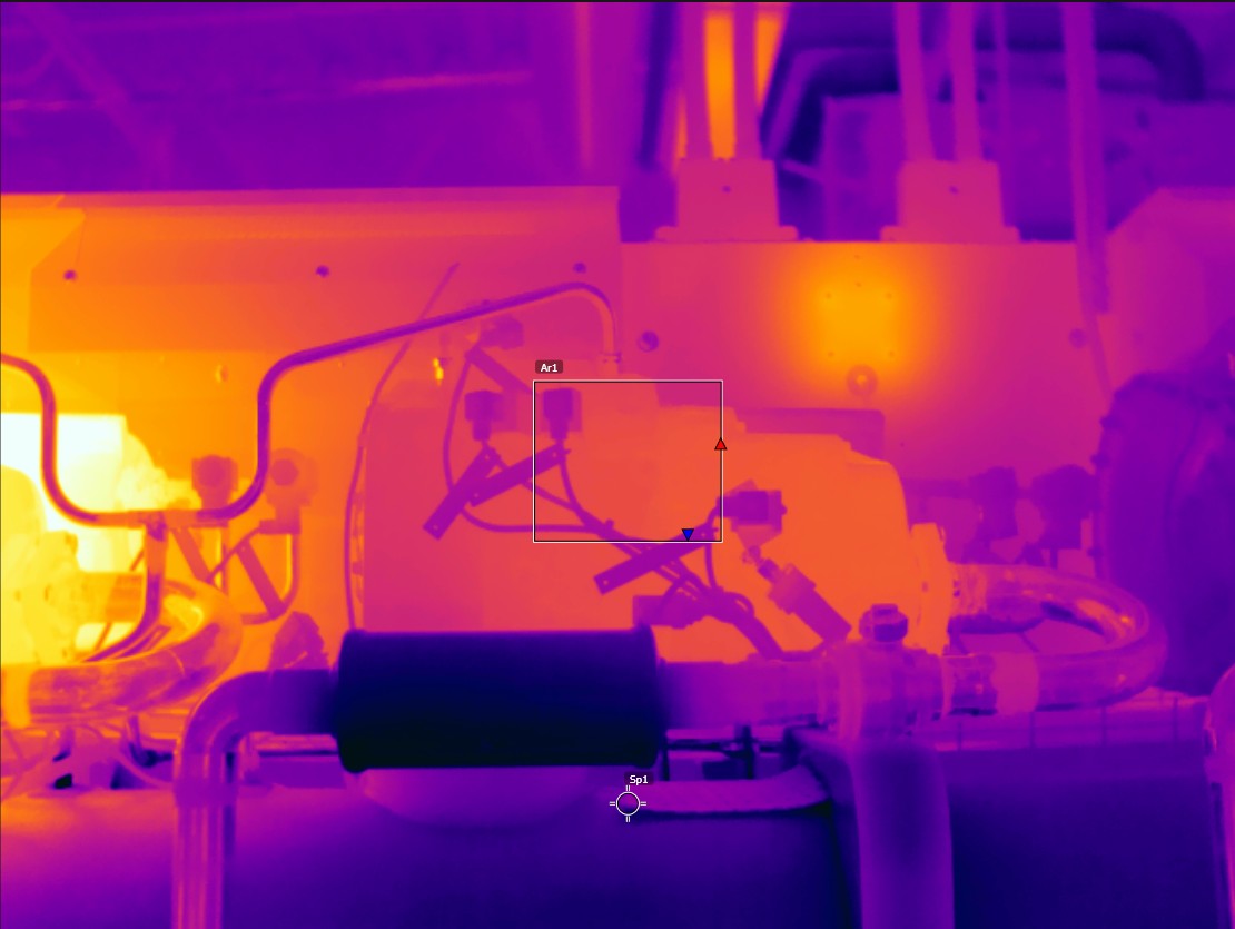
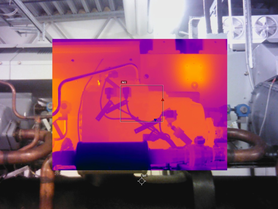
Reference image
Reference image
Use the reference image for aiming support. It is possible to switch between the infrared and visual reference image.
With the overlay functionality enabled, the reference image is transparent and is shown over the live image.
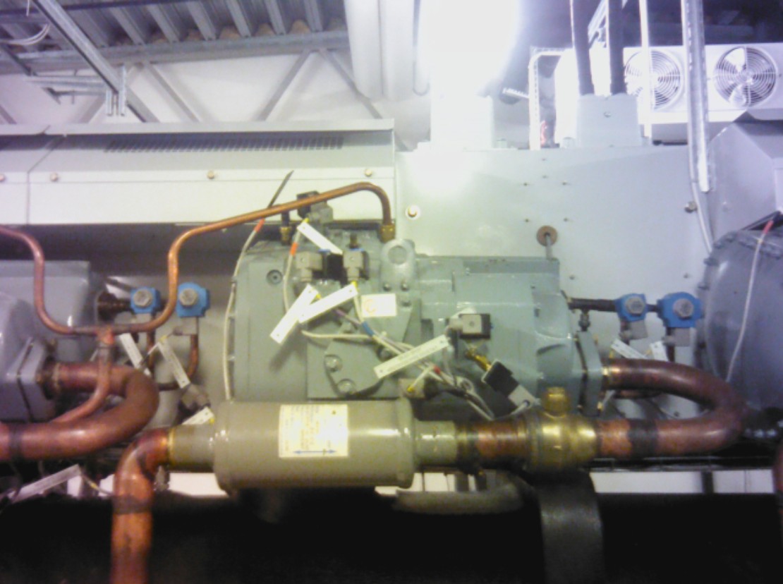
Figure 2.
Show or hide the reference image.
Switch between the infrared and visual reference images.
Enable or disable the overlay functionality. When enabled, the reference image is transparent.
Maximize or minimize the reference image. When maximized, the reference image fully covers the screen.
Drop-down menu
To display the drop-down menu, click on the current point indicator.
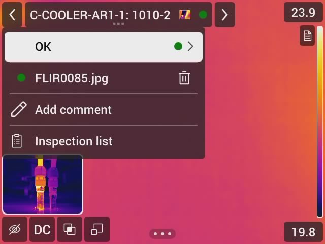
Figure 3.
In the drop-down menu it is possible to:
Set the status of the current inspection point.
View the filenames of images saved for this inspection point.
Add comments for the current inspection point.
Open the inspection list, see section Inspection list.
Inspection list
The inspection list shows the progress of the inspection and analysis of the results from the inspection points.
The content of the inspection list is defined by the route file. The structure and name of the route comes from the file.
To see the progress and review the results, do the following:
Click on the current point indicator. This displays a drop-down menu.
Click on Inspection list. This displays a list with all inspection routes and their progress.
Select an item in the list to display the next level in the inspection route structure.
When there is a level with inspection points, their status is shown and if they have any images related to them.
To make changes to an inspection point, click on the inspection point in the list. This will show the live view for that inspection point.
Define the camera behavior settings
To override the Route settings and define the camera behavior settings select Settings > Routing > Inspection settings > Use Route settings = Off.
Camera behavior settings:
Auto next, the setting defines if the camera, after saving an image, automatically will set the default status and go to the next inspection point. If most of the inspection points will have the default status, you can activate the setting to save the inspection time. If you often want to set the status or add comments to the inspection points, it may be better to disable the setting.
Default status, a submenu used to select the status to be set when an image is saved. The options in the submenu come from the route file.
Require image, the setting defines if the image must be saved before it is possible to set the status of an inspection point.
Delete empty inspection points, the setting defines if all empty inspection points (no image and no status) will be removed from the inspection file when the inspection is finished.
Settings and parameters from the reference images
The camera can be configured to use the settings and parameters from the reference images. At each inspection point, the camera will automatically apply the same measurement tools, measurement parameters, temperature scale values, and color palette as in the reference image. To apply the settings and parameters from the reference images:
Select Settings > Routing > Inspection settings > Reference image.
To apply the parameter settings from each Reference image, select Apply parameters = On.
To select what parameters to apply, select Parameters.