Field wiring and connections
Connectors overview
|
Connector |
Type |
Function |
|
ETH/PoE |
M12 X-coded female 8-pin (rear) |
Ethernet data + PoE power (primary power source for A40, A50, and A70) |
|
PWR/DIG.I/O |
M12 A-coded male 12-pin (rear) |
Alternate DC power input (all models) + alarm/trouble/digital I/O signals |
|
RS232/RS485 |
M8 A-coded male 4-pin (rear) |
Serial communication (optional) |
Power/Digital I/O connector and cable
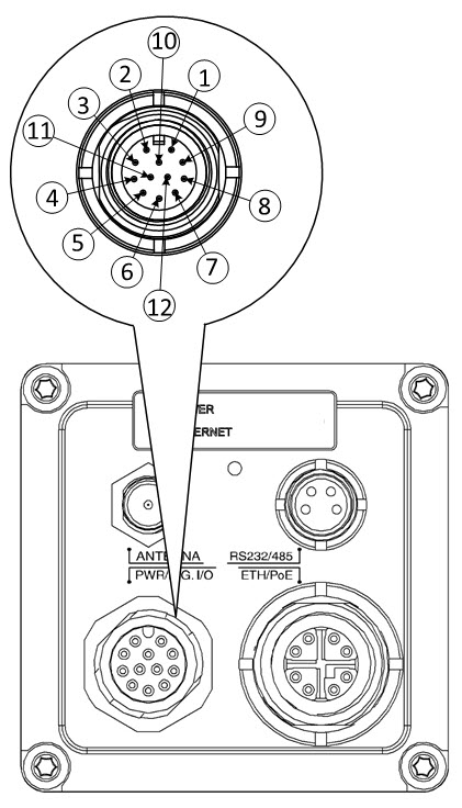
Figure 1. Male A-coded M12 Power/Digital I/O connector |
|||
|
Pin |
Configuration |
||
|
1 |
EXTPWR_RTN |
||
|
2 |
EXTPWR_IN |
||
|
3 |
FAULT_A |
||
|
4 |
FAULT_B |
||
|
5 |
DIGOUT1A |
||
|
6 |
DIGOUT1B |
||
|
7 |
DIGOUT2A |
||
|
8 |
DIGOUT2B |
||
|
9 |
DIGIN1 |
||
|
10 |
DIGIN2 |
||
|
11 |
Not Connected |
||
|
12 |
DIGIN_RTN |
||
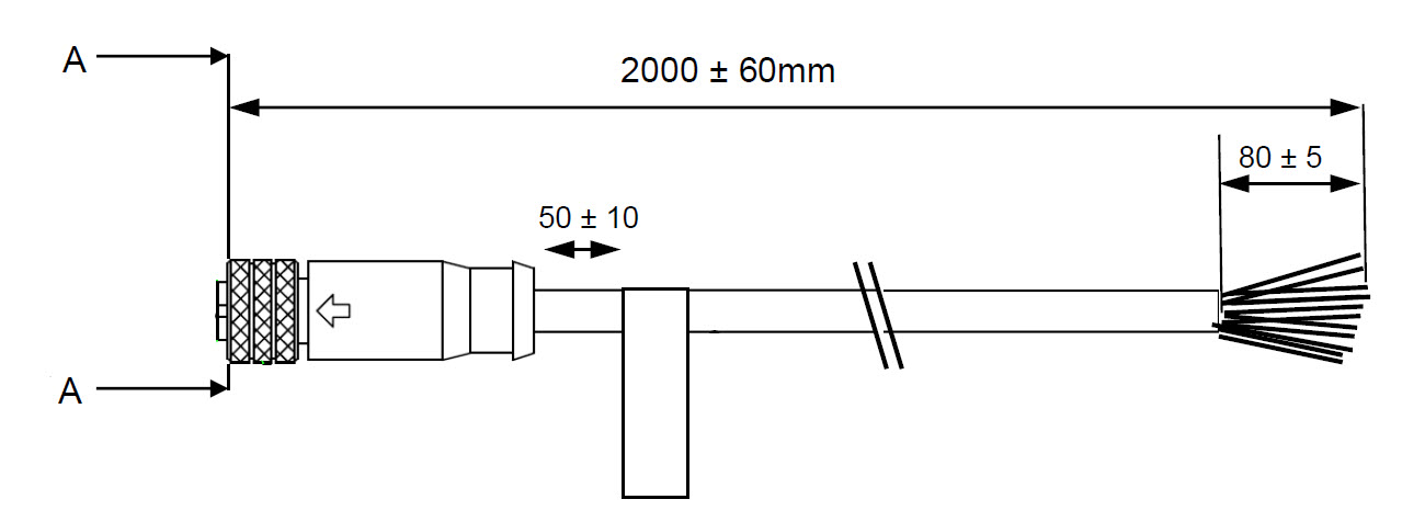
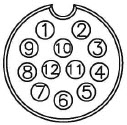
Figure 2. Cable M12 to pigtail |
Section A—A |
Wire colour |
|
|
1 |
Black |
||
|
2 |
Red |
||
|
3 |
Green |
||
|
4 |
Purple |
||
|
5 |
Yellow |
||
|
6 |
Pink |
||
|
7 |
Orange |
||
|
8 |
Brown |
||
|
9 |
White |
||
|
10 |
Grey |
||
|
11 |
Light blue |
||
|
12 |
Blue |
Connection to the fire alarm control panel (FACP)
The detector provides power-limited, dry-contact alarm and trouble outputs for connection to the initiating device circuit (IDC) of a fire alarm control panel listed for fire alarm service, or to listed addressable monitor modules. All lead labels in this section match the pin configuration table in section Power/Digital I/O connector and cable. Conductor types and sizes for the field wiring are specified in section Wire Type and Conductor Size — Signal Circuits.
Detector circuits and leads
|
Function |
Leads (pin, lable, wire color) |
Contact type and action |
|
Alarm output |
Pin 5, DIGOUT1A, yellow Pin. DIGOUT1B, pink |
Dry contact, normally open. Closes on alarm. |
|
Trouble (fault) out put |
Pin 3. FAULT_A, green Pin 4. FAULT_B, purple |
Dry contact, normally closed. Opens on a detector fault condition or on loss of operating power. |
|
External DC power (alternative to PoE) |
Pin 2. EXTPWR_IN, red Pin 1. EXTPWR_RTN, black |
18–56 V DC supply input, power-limited. See External DC power (Alternative). |
The alarm and trouble outputs are dry (voltage-free) contacts, implemented as solid-state opto relays, they do not source voltage. All circuit voltage and current are supplied by the FACP initiating device circuit through the contact. Do not apply voltage or current exceeding the supplementary circuit ratings in section Wire Type and Conductor Size — Signal Circuits.
The detector connects to the field wiring through the M12 A-coded 12-pin pigtail assembly. Each pigtail lead used for the IDC shall be spliced to one incoming and one outgoing field conductor so that the connection is monitored. Do not tap a lead onto an unbroken field conductor.
For system monitoring — For leads DIGOUT1A and DIGOUT1B, do not use looped wire. Break wire run to provide monitoring of connections.
Mise en garde
Pour le contrôle des systèmes — Pour les bornes DIGOUT1A et DIGOUT1B, ne pas utiliser de fil enroulé sous les bornes. Couper le câblage pour assurer la surveillance des raccordements.
Class B (Style B) connection
Figure 3 shows two detectors connected directly to a Class B (Style B) initiating device circuit of a conventional FACP. For a Class A (Style D) system, see section Class A (Style D) connection.
Connect the DIGOUT1A and DIGOUT1B leads of each detector across the IDC conductors. Splice each lead to one incoming and one outgoing conductor.
Install the end-of-line resistor (EOLR) specified by the FACP manufacturer at the last detector on the circuit.
Connect the FAULT_A and FAULT_B leads of all detectors in series on a supervised trouble or supervisory circuit, terminated with the EOLR specified by the FACP manufacturer, so that a detector fault condition or loss of operating power at any detector results in a trouble signal at the FACP. This supervised connection supports the supervision provisions of NFPA 72 section 17.12. See section Trouble output test procedure for the trouble output test.
Power each detector from PoE in accordance with section Supply circuit, power over Ethernet, or from a regulated, power-limited DC supply in accordance with section External DC power (Alternative). Where standby (secondary) power is required, see section Battery Backup, calculation of 24 hours standby time.
Use conductors in accordance with section Wire Type and Conductor Size — Signal Circuits. FACP-side field wiring shall be a minimum of 18 AWG (0.82 mm²), the detector M12 pigtail assembly uses 26 AWG conductors per UL 2684 section 14.4.2(b).
After installation, verify operation in accordance with section Go/No-Go test procedure and trouble output test procedure.
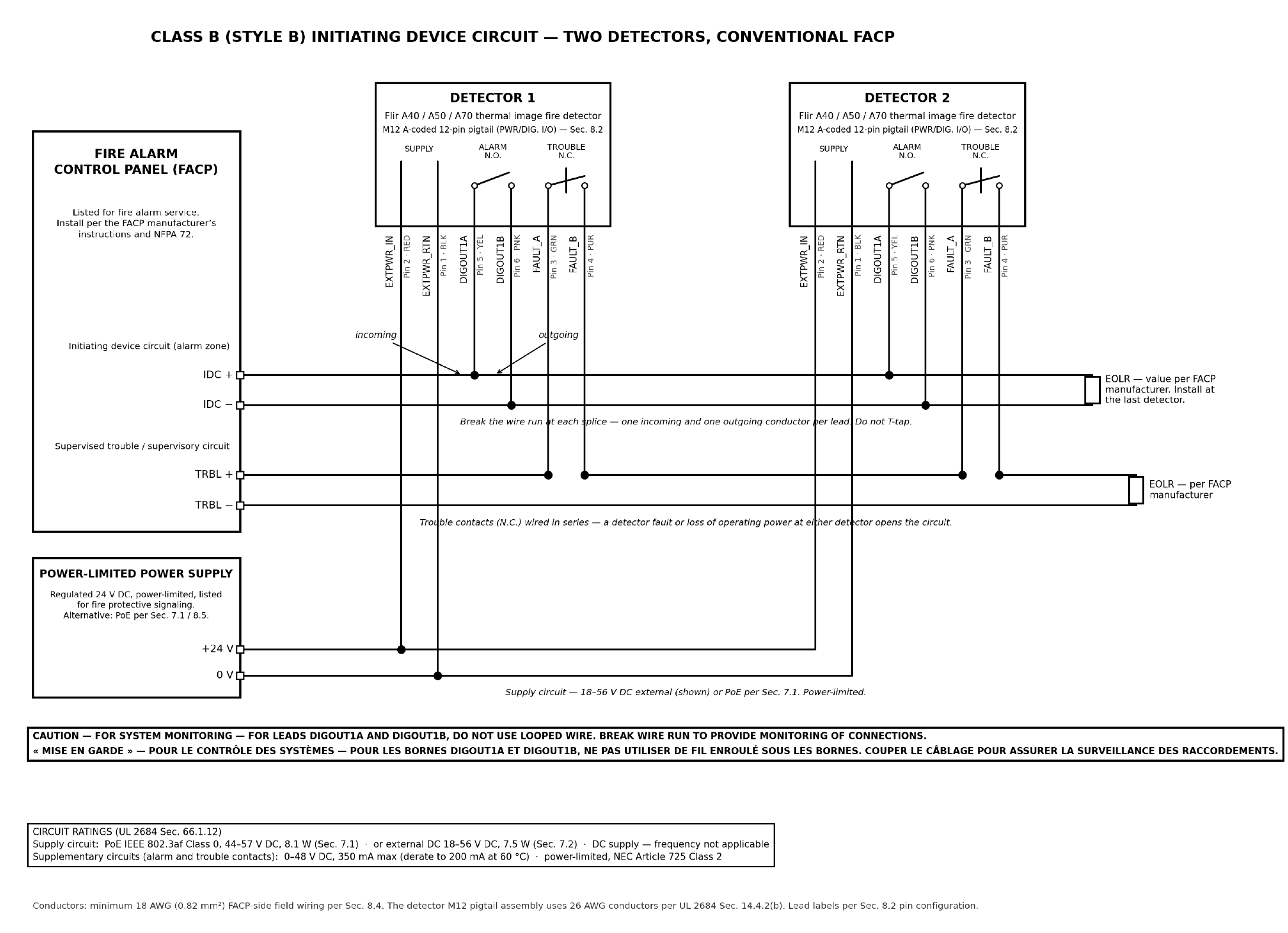
Figure 3. Class B (style B) initiating device circuit — two detectors, conventional fire alarm control panel.
Class A (Style D) connection
Full Class A (Style D) survivability for these detectors is achieved by carrying the alarm and trouble signals on listed addressable monitor modules and running the addressable signaling line circuit (SLC) as Class A. The redundant, supervised pathway lives on the SLC data loop, each detector dry contact is a short, locally supervised drop to a module input. This arrangement also provides individual annunciation of each detector at the FACP. Figure 4 shows two detectors connected in this way.
A normally-closed contact signals by opening, which is the same electrical event as a single-conductor open. Series normally-closed trouble contacts run directly across a conventional Class A initiating device circuit therefore do not provide functional Class A survivability for the trouble path. Carrying survivability on the SLC, as described here, resolves this conflict and is the recommended method.
Run the SLC as Class A. Route the outgoing and return legs separately in accordance with the Class A pathway separation requirements of NFPA 72 and the authority having jurisdiction. Land each monitor module on the SLC.
Alarm output. Connect the DIGOUT1A and DIGOUT1B leads of each detector to a monitor module input configured for a Class A normally-open initiating device. Wire the input out-and-return, no end-of-line resistor is used.
Trouble output. Connect the FAULT_A and FAULT_B leads of each detector to a supervised monitor module input. Locate the end-of-line resistor at the detector and configure the module input, per the module manufacturer’s instructions, so that a contact opening is annunciated as the active (trouble) condition, distinct from a wiring fault. This supports the supervision provisions of NFPA 72 section 17.12. See section Trouble output test procedure for the trouble output test.
Use one module input per detector output so that each detector is individually annunciated at the FACP.
Power each detector from PoE in accordance with section Supply circuit, power over Ethernet, or from a regulated, power-limited DC supply in accordance with section External DC power (Alternative). Where standby (secondary) power is required, see section Battery Backup, calculation of 24 hours standby time.
Use conductors in accordance with section Wire Type and Conductor Size — Signal Circuits. FACP-side field wiring shall be a minimum of 18 AWG (0.82 mm²); the detector M12 pigtail assembly uses 26 AWG conductors per UL 2684 section 14.4.2(b). Module input configuration, EOLR values, and personality codes are per the module manufacturer’s listing.
A listed Class A/B monitor module providing a Class A normally-open initiating input is suitable, for example, Edwards SIGA-UM or SIGA-MAB personality codes 9–12. Vendor selection is the system designer’s, any equivalent listed module is acceptable. After installation, verify operation in accordance with section Inspection, testing, and maintenance.
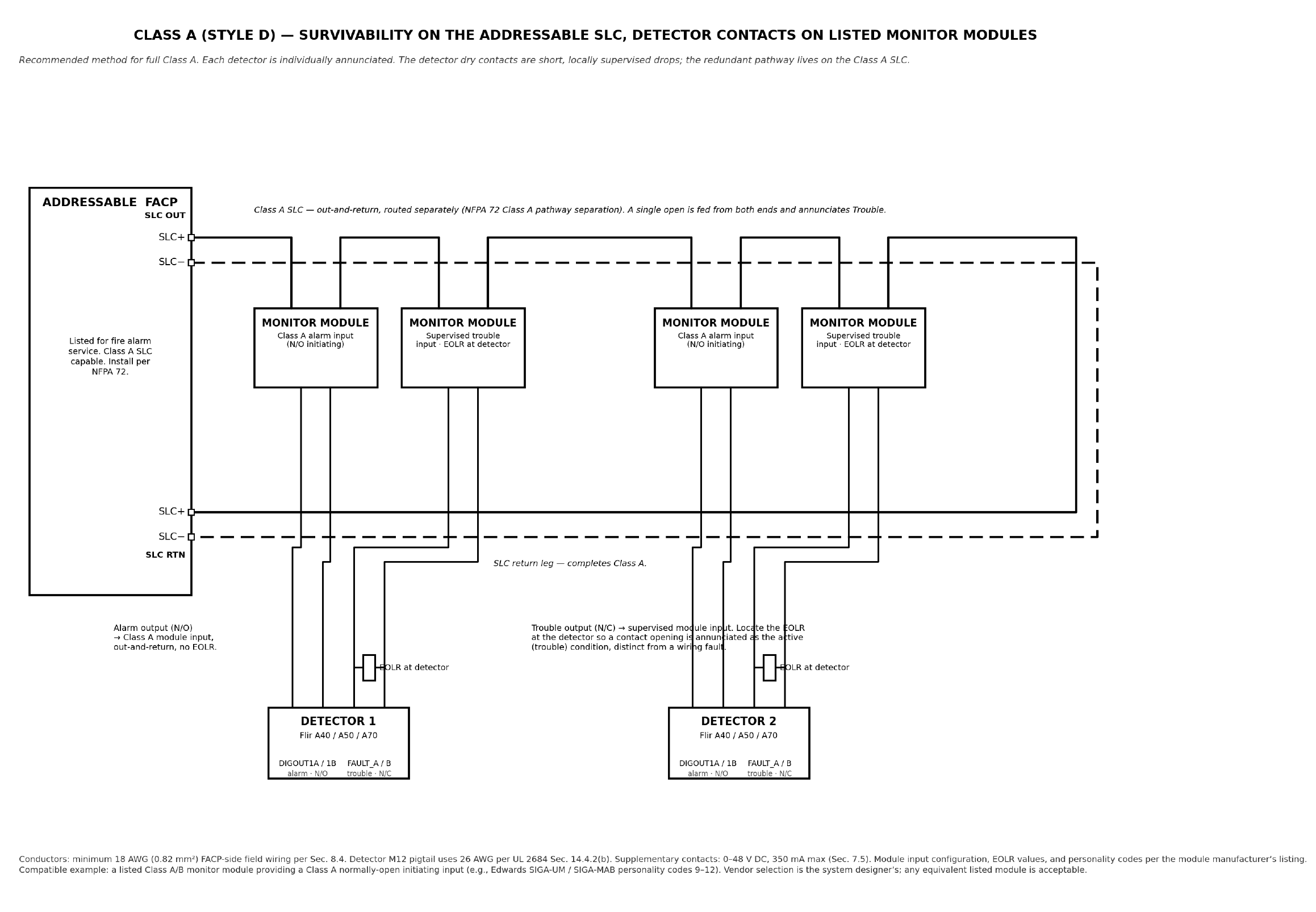
Figure 4. Class A (Style D) — survivability on the addressable SLC, detector contacts on listed monitor modules.
Circuit ratings
|
Circuit |
Rating |
|
Supply circuit — PoE (primary, A50/A70) |
IEEE 802.3af Class 0, 44–57 V DC, 8.1 W typical. DC supply, frequency not applicable. See Supply circuit, power over Ethernet. |
|
Supply circuit — external DC (alternative) |
18–56 V DC, 7.5 W typical. DC supply — frequency not applicable. See External DC power (Alternative). |
|
Supplementary circuits — alarm and trouble contacts |
0–48 V DC, 350 mA maximum (derate to 200 mA at 60 °C). Power-limited, NEC Article 725 Class 2. See Supplementary I/O circuits. |
Installations in Canada (ULC)
In Canada, there are two official languages, English and French. Some Canadian authorities may require markings and installation instructions to be provided in both official languages. The wiring diagram caution in this section is provided in English and French in accordance with UL 2684 Annex E. Installations in Canada shall conform to CAN/ULC-S524 and the requirements of the authority having jurisdiction.
Wire Type and Conductor Size — Signal Circuits
The following specifications apply to IDC alarm/trouble signal wiring.
Above ground runs (interior and exterior exposed):
Minimum 18 AWG (0.82 mm²) copper, twisted pair, overall shielded.
Fire alarm cable rated for the application environment (plenum, riser, or general purpose as required).
Shield grounded at one point only, at the FACP or addressable I/O module. Do not ground at both ends, a double-grounded shield creates a ground loop that induces the interference it is intended to prevent.
Stranded conductors are recommended for cables subject to vibration or bending.
Subterranean/underground runs:
Option A. Minimum 18 AWG, twisted pair, shielded, direct burial rated jacket.
Option B. Standard shielded fire alarm cable (as above) installed in a sealed, watertight conduit. The conduit ends must be sealed with applicable compound to prevent moisture ingress and condensation migration.
Maximum distance and conductor size reference:
Max. run
Min. run
Typical loop resistance
Notes
1,000 ft (305 m)
18 AWG
≈ 6.5 Ω
Standard — most installations
2,000 ft (610 m)
18 AWG
≈ 13 Ω
Verify against FACP IDC impedance tolerance
2,000 ft (610 m)
16 AWG
≈ 8 Ω
Recommended for runs approaching 2,000 ft
3,000 ft (914 m)
16 AWG
≈ 12 Ω
Consult FACP manufacturer for circuit tolerance
Conduit separation and EMI limitation:
Signal wiring must be installed per NEC Article 725 Class 2 circuit requirements.
Signal wiring shall not share a conduit, raceway, or cable tray with power wiring above 30 V, including motor leads, VFD output conductors, or building power circuits.
Minimum separation from power conduit: 50 mm (2 in) for parallel runs in standard environments.
In industrial environments with VFDs, large motors, welding equipment, or high-current bus ducts: 300 mm (12 in) minimum separation for parallel runs.
Where required separation cannot be achieved, use shielded cable with single-point grounding as specified above.
Cross power conduit at 90° where crossing is unavoidable.
Network connection
Use only PoE power supply equipment that meets the requirements of UL 60950-1 or UL 62368-1 and meets the requirements of UL 2684 section 10, see section Compatible PoE power sourcing equipment.
Connect the M12 X-coded to RJ45 Ethernet cable between the detector ETH/PoE port and a PoE-capable port on the network switch.
The PoE switch port is IEEE 802.3af Class 0 capable (minimum 15.4 W available per port).
The detector is set to DHCP by default. Use Flir IP Config (download at support.flir.com) to identify the camera on the network by its MAC address (printed on the detector label).
Assign a static IP address appropriate for the fire alarm system network. Isolate the fire alarm camera network on a dedicated VLAN where possible.
The Power/error indicator LED should flash green to confirm network connection and normal operation.