Image editor
This chapter describes how to use the image editor.
General
The FLIR Thermal Studio application includes an embedded image editor where you can edit thermal images and sequences (videos).
To open the image editor, do one of the following:
Double-click the image.
Right-click the image and then click Edit.
In the Library tab, click Edit image in the right pane.
To open the image editor with Comparison view, see section Comparison View.
Navigation
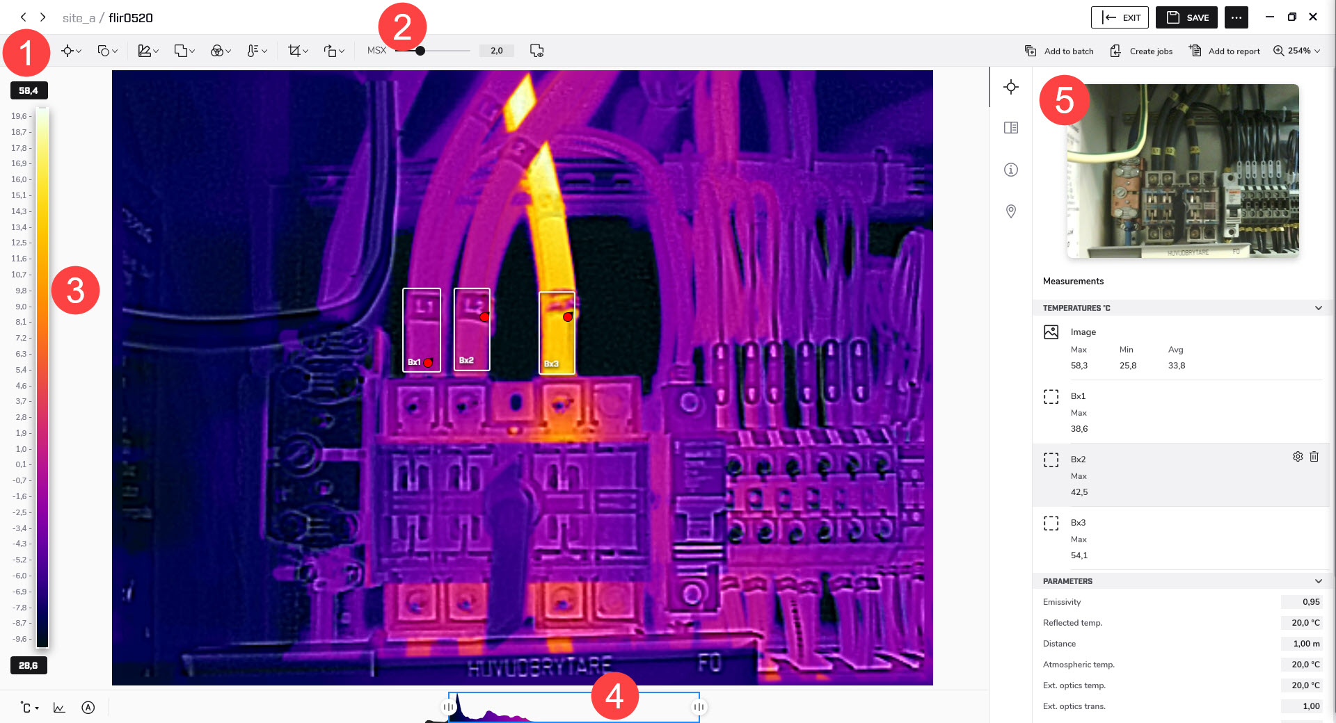
Toolbar
The toolbar includes options such as adding measurements, changing palettes, and controlling isotherms and the color distribution.
Current fusion mode
Displays the currently selected fusion mode and any additional mode settings.
Temperature scale
Temperature span and level control
Use the controls to adjust the temperature scale.
Properties pane
Use the vertical pane toolbar to select display of measurements, notes, camera details, and geolocation.
Temperature span and levels
At the bottom of the infrared image you have two sliders. By dragging these sliders to the left or to the right, you can change the top and bottom levels of the temperature span. If you change the span to temperatures closer to the temperature of the object you are analyzing, it will be easier to analyze any temperature anomalies.
To move the temperature span, click and hold the temperature span and then move it into position.
To change the bottom and top levels of the temperature span, click and drag the left (bottom level) and the right (top level) sliders into position.
To auto-adjust, double-click the span and level control. See also section Auto-adjust control.
To use the full camera range, right-click the span and level control.
Auto-adjust control
When you auto-adjust a thermal image, you adjust it for the best image brightness and contrast. This means that the color information is distributed over the existing temperatures of the image.
In some situations the image may contain very hot or very cold areas outside your area of interest. In such cases you might want to exclude those areas and use the color information only for the temperatures in your area of interest. You can do so by defining an auto-adjust region.
To auto-adjust an image, do one of the following:
Double-click the temperature span and level control at the bottom of the window.
At the lower left corner, click the Enable scale auto adjust button.
To define an auto-adjust region, follow this procedure:
On the top toolbar, click Add measurement, and then click Rectangle.
Click the image to place the start point. Drag the pointer to the desired size, and then click to place the end point.
Right-click the rectangle, and then click Auto level and span from rectangle.
Move and change the size of the rectangle to suit your area of interest. Note how the image changes as you make your changes.
Sketch
You can add an image, e.g. a logo, on top of the image.
On the top toolbar, click Sketch, and then click Replace sketch.
Browse for the image to display on top of the currently edited image.
Use the Enable sketch check box to show/hide the sketch image.
Measurement tool
You can add one or more measurement tools to the image, such as Spotmeter, Rectangle, and Polygon.
Each measurement tool has its own settings, which are available in the Measurements section of the properties pane.
Add a measurement tool
On the top toolbar, click Add measurement, and then click the preferred tool.
Click the image to place the start point. Drag the pointer to the desired size, and then click to place the end point. For the Polygon and Polyline shapes, click to place the start point, and then drag the pointer to the next point. Continue until you have the desired shape. Finish by right-clicking.
The properties for the tool are shown in the Measurements section of the properties pane.
Edit a measurement tool
To move the tool, click and hold the tool, and then move it into position.
To change the size, click and hold the outline of the tool, and then drag it to the desired size and shape.
Change settings of a measurement tool
The tool settings are available in the Measurements section of the properties pane.
To display the tool settings, do one of the following:
Right-click the tool, and then click Measurement settings.
In the Measurements section of the properties pane, point at the tool and then click the settings button that appears.
Delete a measurement tool
To display the tool settings, do one of the following:
Right-click the tool, and then click Delete.
In the Measurements section of the properties pane, point at the tool and then click the trash bin button that appears.
Use the Delta tool
The Delta tool gives the difference (delta) between two measurement results, or between a measurement result and a reference temperature.
On the top toolbar, click Add measurement, and then click Delta.
In the Measurements section of the properties pane, point at the delta tool and then click the settings button that appears.
In the properties pane, select the measurement tools or reference temperature you want to use as sources.
When completed, click Done at the bottom of the properties pane.
Use the Magic wand
Use the Magic wand to capture an area in the image based on pixel temperature. This is similar to the Polygon measurement tool but more advanced and easier to use when you want to capture and measure more complex shapes.
On the top toolbar, click Add measurement, and then click Magic wand.
Click to place the tool in the image. An area that has the same temperature as the selected point appears in the image.
In the Measurements section of the properties pane, move the Tolerance slider to adjust the area and include pixels that are close in temperature to the selected point.
Export to a csv file
Use the Export to csv functionality to export detailed temperature information. The export will include the temperature values of every pixel within the selected measurement tool.
Right-click the tool, and then click Export to csv.
In the settings dialog, select the preferred export options, and then click Ok.
In the Save as dialog, browse to the folder where you want to store the exported file, and then click Save.
Use coverage
Use the Coverage functionality to see, as a percentage, the number of pixels in an area that are above or below a certain temperature. The area is defined by the outline of a measurement tool, such as a rectangle or ellipse.
The coverage percentage is displayed in the Measurements section of the properties pane. It is also possible to apply a contrasting color to all pixels in the area that meet the temperature setting.
In the Measurements section of the properties pane, point at the tool and then click the settings button that appears.
Select the Use coverage check box.
Select the Above and/or Below boxes and set the temperature limit.
Use the Isotherm check box to apply a contrasting color to the pixels that meet the temperature setting.
Shape
You can add shapes to the images, such as arrows, comments, and alerts.
Add a shape
On the top toolbar, click Add new shape, and then click the preferred shape.
To move the shape, click and hold the shape, and then move it into position.
To change the size, click and hold the outline of the shape, and then move it to the desired size and shape.
To change the shape settings, right-click the shape and then click Shape settings.
Palette
You can change the palette that is used to display the temperatures within an image. A different palette can make it easier to analyze the image. The FLIR Thermal Studio application comes with a set of predefined palettes, but custom palettes can also be used.
To change the palette, follow this procedure:
On the top toolbar, click Select palette.
Select one of the predefined palettes, or click From file to select a custom palette.
To export a palette, follow this procedure:
On the top toolbar, click Select palette.
Right-click the palette, and then click Export palette.
In the Save as dialog, browse to the folder where you want to store the exported palette, and then click Save.
Fusion mode
Use the Fusion mode feature to mix a visual image with its corresponding thermal image. The following fusion modes are available:
MSX (Multi Spectral Dynamic Imaging)
Displays a thermal image where the edges of the objects are enhanced. The thermal–visual balance can be adjusted.
Thermal only
Displays a fully thermal image.
Thermal fusion
Displays a visual image with some parts displayed as a thermal image, depending on the temperature limits.
Blending
Displays a blended image that uses a mix of thermal image pixels and visual image pixels. The thermal–visual balance can be adjusted.
Picture in picture
Displays a thermal image frame on top of a visual image.
Visual only
Displays a fully visual image.
To set the fusion mode, follow this procedure:
On the top toolbar, click Fusion mode.
Select the preferred fusion mode.
Note that some of the modes have additional settings:
MSX
Move the MSX slider to show more or fewer contours in the image.
If necessary, click the Adjust fusion alignment button to manually align the images.
Thermal fusion
Move the sliders to change the temperature limits.
If necessary, click the Adjust fusion alignment button to manually align the images.
Select the Black and white check box for a black and white visual image.
Blending
Move the Blending slider to change the proportions of the thermal image and the visual image.
If necessary, click the Adjust fusion alignment button to manually align the images.
Select the Black and white check box for a black and white visual image.
Picture in picture
Select the Picture in picture check box, and then move the slider to change the proportions of the thermal image and the visual image.
If necessary, click the Adjust fusion alignment button to manually align the images.
Click the Adjust picture-in-picture rectangle button to move the rectangle or change its size.
Select the Black and white check box for a black and white visual image.
Visual only
Select the Black and white check box for a black and white visual image.
Color distribution
Use the Color distribution option to change the distribution of colors in the image. A different color distribution can make it easier to analyze the image more thoroughly. The following distributions are available:
Histogram equalization
The color information is distributed over the existing temperatures of the image. This method of distributing the information is especially successful when the image contains few peaks at very high temperature values.
Signal linear
The color information in the image is distributed linearly with respect to the signal values of the pixels.
Temperature linear
The color information in the image is distributed linearly with respect to the temperature values of the pixels.
Digital Detail Enhancement (DDE)
The high-frequency content in the image, such as edges and corners, are enhanced to increase the visibility of details.
To change the color distribution, follow this procedure:
On the top toolbar, click Color distribution.
Click one of the available color distributions.
Isotherms control
Using isotherms is a good method to easily discover anomalies in a thermal image. The isotherm functionality applies a contrasting color to all pixels with a temperature above, below, or within a certain temperature interval. You can also create your own isotherm formulas.
For building inspection, there are specific alarms for detection of humidity, insulation, and condensation issues.
To add an isotherm or alarm, follow this procedure:
On the top toolbar, click Isotherms control.
Select an isotherm or alarm.
In the Measurements section of the properties pane, define the settings for the isotherm or alarm.
Crop an image
Use the Crop image option to trim the image. Provided that the cropped image has not been saved, it is possible to revert to the original image size.
To crop an image, follow this procedure:
On the top toolbar, click Crop image.
Select the Show crop rectangle check box. A dotted rectangle is added to the center of the image.
To move the rectangle, click and hold the rectangle, and then move it into position.
To change the size, click and hold the outline of the rectangle, and then move it to the desired size and shape.
To exit, click one of the icons in the bottom right corner of the rectangle:
To confirm the change, click the check mark.
To cancel the change, click the cross.
To revert to the uncropped image, follow this procedure:
On the top toolbar, click Crop image.
Click Reset image.
Image rotation
To rotate an image, follow this procedure:
On the top toolbar, click Image rotation.
Click one of the rotation options.
As an alternative, type the desired angle in the Angle text box.
Filter
Filters for enhanced gas visualization are available for video files (.seq and .csq).
Using the high sensitivity mode and pixel binding filters can make it easier to identify gas leaks.
Show a profile plot
The plot shows the temperature profile along a line or rectangle in the image.
At the lower left corner, click the Show profile plot button.
On the top toolbar, click Add measurement, and then click Line.
In the image, draw a measurement line of interest. The plot now shows the temperature profile along the drawn measurement line.
To change the plot settings, click the Settings button to the right of the plot.
Show a time-temperature plot
This plot is available for video files (.seq and .csq). The plot shows the temperature fluctuations over time for the image statistics (max, min, average) and for selected measurement tools.
At the lower left corner, click Show profile plot.
At the lower left corner, click Sequence. The plots for the image statistics (max, min, average) are displayed. Each plot shows how the temperature changes with time.
To change the plot settings, click the Settings button to the right of the plot.
To add a new plot, do one of the following:
On the Settings pane, click Add plot, and then select a measurement and a type of value.
Right-click a measurement tool in the image, click Sequence plot, and then select the type of value.
Video controls
When you open a video file in the image editor, video controls such as play/pause, auto repeat, and save a snapshot are available at the bottom of the window.
To save a part of the video as a separate file, follow this procedure:
At the lower left corner, click Add marker.
On the time line, click and drag the markers into position.
At the lower left corner, click Save selection.
In the dialog, browse to the folder where you want to store the exported file, and then click OK.
Save changes
To save the changes in the original file, do one of the following:
At the top right corner, click Save.
At the top right corner, click Exit. In the Unsaved changes dialog, click Yes.
To save the image with the changes in a new file, click the button with three dots at the top right corner and then click Save as.
Comparison View
The Comparison view is an efficient way to compare similar images and edit them at the same time. The Comparison view is available from the library tab and from the routing tab while editing an inspection file.
Open in Library
Select two or more images by holding CTRL and SHIFT at the same time on your keyboard.
When selected, right click with the mouse and then press edit.
This opens the Comparison view screen.
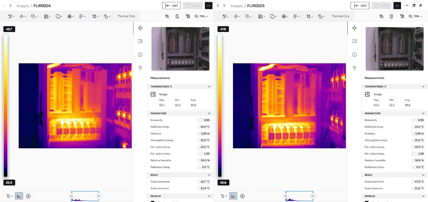
In the Comparison view, you can edit both selected images on the right and on the left.
If you have more images in the same location folder, you can use the arrows in the top menu to proceed to the next image.
To exit the Comparison view, press exit in the top right corner.
Press once to enter normal editor mode.
Press twice to return to the library screen.
Open in inspection file editor
For more information on inspection files, see Create inspection report.
Open a finished .route file that contains reference image(s).
Select the inspection point you want to compare.
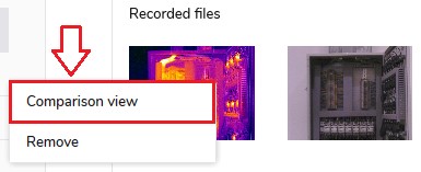
Right click on the right pane of the image.
Select Comparison view.
 Note
In the Comparison view you can only edit the inspection image. The reference image can not be edited.
To exit the Comparison view, press exit in the top right corner.
Press once to enter normal editor mode.
Press twice to return to the library screen.