Installation
Camera parts
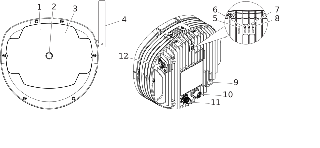
Figure 1.
|
1. Microphone array |
7. LINK LED |
|
2. Video camera |
8. ACT LED |
|
3. Dust cover |
9. VESA 100 x 100 mounting holes |
|
4. Antenna |
10. PoE (Power Over Ethernet) connector |
|
5. Factory button |
11. I/O connector |
|
6. Power LED |
12. Wi-Fi antenna connector |
Installation guide
Safety information
Install the product exactly as described in this section. Deviations may compromise protective safeguards.
Make sure the mounting location supports the mass of the device and expected mechanical loads (including shock and vibration).
Disconnect and lock out the power supply before connecting electricity or performing any service. Only Flir‑authorized service personnel may open the camera for service.
Before operating the camera, you must read, understand, and follow the warnings, cautions, and notes in the User manual, see section Safety information. The User manual is available online, see section Online documentation.
Mount the camera
The device’s mounting points are compatible with most VESA 100 x 100 mounting adapters.
Make sure that the mounting adapters lower bracket does not interfere with I/O and PoE connectors.
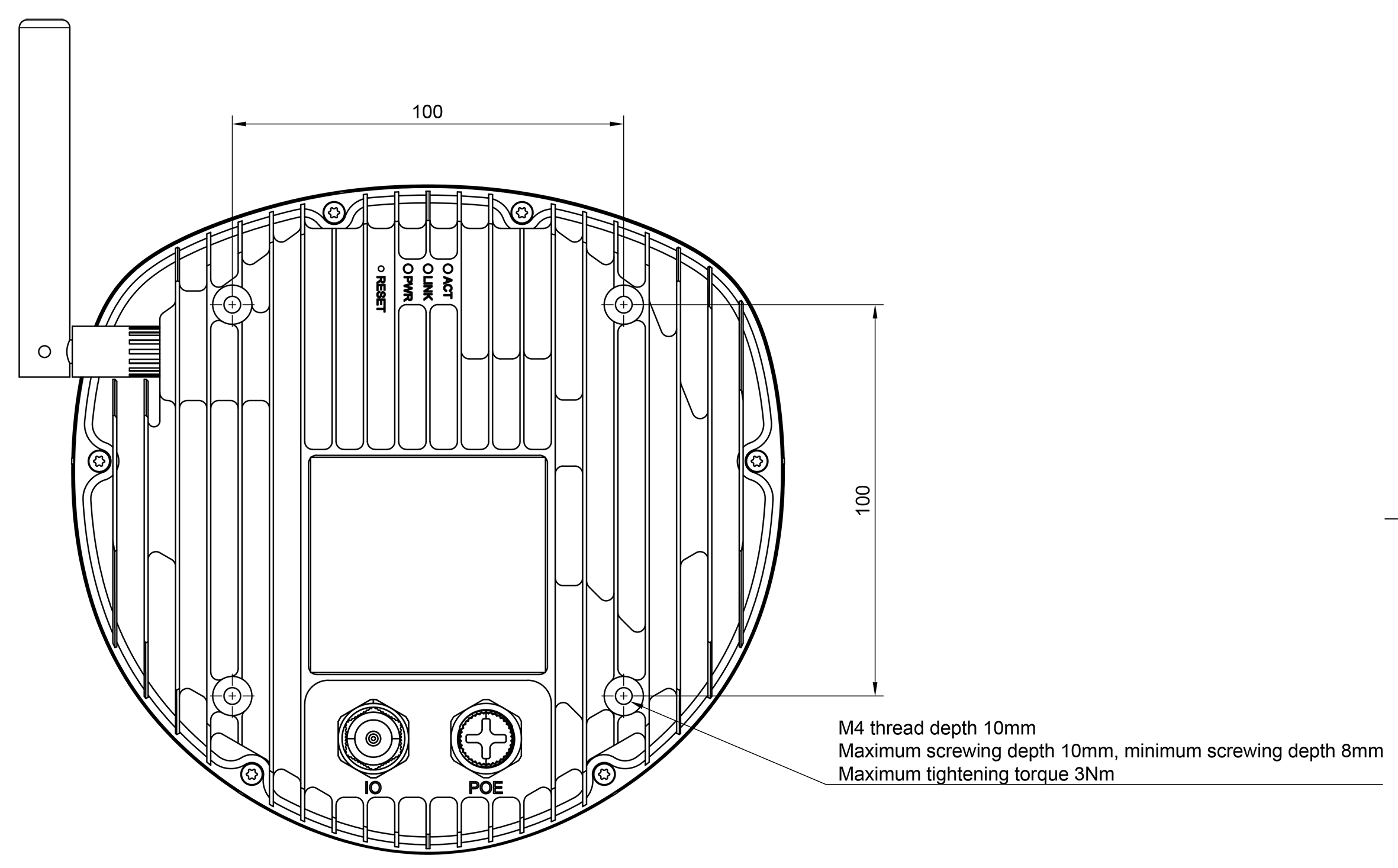
Figure 2.
Make sure the mounting surface is flat, clean, and load‑bearing.
Use correct fasteners for the mounting surface/material (wall/ceiling/panel/rack, etc., as applicable).
To achieve optimal cooling, install the device with the cooling fins in an upright position to improve natural convection.
Use only grade 8.8 or 12.9 screws. Tighten each fastener to a maximum of 3 Nm.
Make sure that the enclosure is secure and cannot shift, tilt, or fall under expected service loads.
Mechanical fasteners
Threading: M4
Maximum screw-in depth: 10 mm
Minimum thread engagement: 8 mm
Connect power and Ethernet (PoE) to the device
Align the connector key/notch on the device and the matching cable.
Push the connector straight in until it is fully seated.
Rotate the locking ring clockwise to hand‑tight only. Do not use tools to tighten the connector.
Use the same procedure to connect the I/O connector, tighten only by hand.
Max length for PoE cable is 100 m.
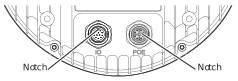
Figure 3.
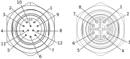
Figure 4. Left: I/O connector pins, Right: PoE connector pins.
|
I/O connector pin |
PoE connector pin |
||
|
Pin number |
Description |
Pin number |
Description |
|
1 |
Not used |
1 |
DA+ |
|
2 |
Not used |
2 |
DA- |
|
3 |
4–20 mA current loop (A) |
3 |
DB+ |
|
4 |
4–20 mA current loop (B) |
4 |
DB- |
|
5 |
Output 1 (A) |
5 |
DD+ |
|
6 |
Output 1 (B) |
6 |
DD- |
|
7 |
Output 2 (A) |
7 |
DC- |
|
8 |
Output 2 (B) |
8 |
DC+ |
|
9 |
Input 1 |
||
|
10 |
Input 2 |
||
|
11 |
Not used |
||
|
12 |
Inputs return |
||
Serial number
A label with the serial number is available at the back of the camera. The serial number is also available in the camera settings, at the bottom of the Settings menu, and on the E-label, see section E-label.
E-label
The E-label is the primary identification plate for the camera. It contains certification and compliance information and other relevant product details. The E-label is available in the configurator tool settings under System > Device.
LED indicators
Power LED light specifications.
Startup and normal operation: The Power LED starts flashing GREEN during boot up. If the camera software has been initialized and normal operation is established, the GREEN light will continue to flash. (Boot time approximately 20 seconds).
Camera software failure: If the software fails to start, the light changes to RED (error state).
Wi-Fi models: The power LED will turn GREEN immediately after power is turned on. The power LED will start flashing GREEN during startup (takes about 20 seconds) to indicate AP mode for alternative wireless setup. The LED will continue to flash until the Wi-Fi connection is established or Wi-Fi is disabled in the settings.
Non Wi-Fi models: The power LED is solid GREEN to indicate that the camera is in normal operation.
Shutdown: No change in LED status. The GREEN light remains on until power is disconnected.
Constant or flashing RED indicates an error in the camera.
When updating the camera software via the configurator tool, the LED will flash ORANGE and the camera will restart after the installation is complete.
Special cases.
Camera software failure: If the software fails to start, the light changes to RED (error
state) after the boot.
Shutdown: The current power LED color remains on until power is disconnected.
Software update: When updating the camera software via the configurator tool, the power LED will flash ORANGE and the camera will restart after the installation is complete.
Factory reset: To start the reset, press and hold the reset button for more than 10 seconds with a long needle. The power light will turn RED.
After holding the reset button for 10 seconds and releasing it, the power LED will flash RED 2–3 times and then turn GREEN, to indicate that the camera is restarting with its settings restored to factory defaults.
ACT and LINK LEDs.
ACT and LINK LEDs indicate that the device is connected to the Ethernet/Wi-Fi. Flashing ACT LED indicates network activity.
Factory reset
A factory reset restores the device to its factory default settings. All user configurations and stored data are removed.
Press and hold the Reset button for more than 10 seconds, the LED turns RED.
When the Factory button is released the LED will flash RED 2-3 times and turn to GREEN to restart the camera.
After the factory reset, use the default username and password to log in to the configurator tool again.